Hello,
This is the first time I am posting on this Forum, so have a little bit kindness please.
I am trying to build a regulated voltage supply with the range of 50–200 Volts and a maximum capability of a 100mA load. But without having to use tubes.
Yes, I can browse this whole part of the Forum to see if there is already published something, but anyway…..
Can somebody help me please?
Joe.
You could use 7 series x LM317 each capable of decreasing 30v, place 220 ohms between adjustment and out, then calculate first output as 170v, second as 140v and so on.
LM317 are available for about 40 cents each if you shop around.
Some care needed so that there would be no possibility of any one regulator processng more than 30v, and a relay contact switch comes to mind, to hold the resistance suitable
at those other settings.
Cheers / Chris
LM317 are available for about 40 cents each if you shop around.
Some care needed so that there would be no possibility of any one regulator processng more than 30v, and a relay contact switch comes to mind, to hold the resistance suitable
at those other settings.
Cheers / Chris
Much easier to use a big power transistor to stand-off the excess voltage. The LM317 itself can supply any voltage, providing the input - output differential is limited to 37v abs max.
You can find suitable examples in many datasheets but in its simplest form , try a HV NPN power transistor upstream of the 317, with :
1. Collector fed by raw +ve supply
2. Emitter feeding input to LM 317*
3. A zener diode of say 6.9v between the base of this TR and the 317 VOUT pin, with a suitable bias resistor from raw +ve supply to zener anode = Tr base junction (though a CCS could be better of course)
The trick here is that all excess voltage - and hence, thermal dissipation - is dropped in the transistor. Choose and heatsink accordingly. 0-400v or far more is not a problem with suitable parts choices.
NB the LM317 additonal protection diodes are absolutely required, and some extra low cuning may also be required to adequately protect all the PSU parts (let alone teh attached circuit) against turn on / off transients.
*some input decoupling, such as 0.1uf/10R in series is recommended here; cap needs full Vin rating.
Last edited:
Hi Joe
This one possible method, and a overall pass transistor is another good method, but since I kicked this reply off I should clarify the use of multiple regulators.
This is what i had in mind with LM317 Regulators where 5x LM317's will give the range you require, however with some gaps between each setting.
So we then need a switch and a relay is ideal with sufficient poles. Purpose of the relay is so you cannot switch the voltage at its maximum from the prior relay, a short across the variable for each range is all that is needed.
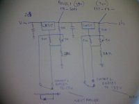
See attached schematic showing first two ranges. The schematic shows variation of 16v possible 2600 ohms approx, so if using 5x regulator there is a gap of 18v when switching the next regulator range down. Hopefully this is not too much of a problem.
If set between adjustment and output is 220 ohms we can then design 200v to 50v ( your design requirement ) . being totally adjustable through the whole range by using 9 x LM317 but parts cost goes up.
If you do not mind some gaps and allowing for approx 34v between each we can get away with 5 regulators, in this case the lower resistor is arranged to have 6k gap ie 30k,24k,18k
12k and 8k2
Arrange a input and output capacitor using 1uf 300v on the first regulator. A TO 220 case LM317 when looking front on has its far left pin as adjustment, its output is the middle pin and its input far right
With an LM317 we cannot exceed 37v between input and output. To calculate any given output we use the following formula 1.25x R2/R1 +1 there is also a current term to consider however it is minor in the overall calculation. So R1 is 220 ohms if the lower resistor is 30k we then have a range of 171v to 200v, the second 6k away is 137-171v allowing 34v between each and if the variable is shorted we are observing the requirement of 34v between each regulator.
This is one possible option, parts cost is not too high. Cheers / Chris
This one possible method, and a overall pass transistor is another good method, but since I kicked this reply off I should clarify the use of multiple regulators.
This is what i had in mind with LM317 Regulators where 5x LM317's will give the range you require, however with some gaps between each setting.
So we then need a switch and a relay is ideal with sufficient poles. Purpose of the relay is so you cannot switch the voltage at its maximum from the prior relay, a short across the variable for each range is all that is needed.
See attached schematic showing first two ranges. The schematic shows variation of 16v possible 2600 ohms approx, so if using 5x regulator there is a gap of 18v when switching the next regulator range down. Hopefully this is not too much of a problem.
If set between adjustment and output is 220 ohms we can then design 200v to 50v ( your design requirement ) . being totally adjustable through the whole range by using 9 x LM317 but parts cost goes up.
If you do not mind some gaps and allowing for approx 34v between each we can get away with 5 regulators, in this case the lower resistor is arranged to have 6k gap ie 30k,24k,18k
12k and 8k2
Arrange a input and output capacitor using 1uf 300v on the first regulator. A TO 220 case LM317 when looking front on has its far left pin as adjustment, its output is the middle pin and its input far right
With an LM317 we cannot exceed 37v between input and output. To calculate any given output we use the following formula 1.25x R2/R1 +1 there is also a current term to consider however it is minor in the overall calculation. So R1 is 220 ohms if the lower resistor is 30k we then have a range of 171v to 200v, the second 6k away is 137-171v allowing 34v between each and if the variable is shorted we are observing the requirement of 34v between each regulator.
This is one possible option, parts cost is not too high. Cheers / Chris
Attachments
Last edited:
sofasud,
Yes, my intention is to use the supply as a bench instument. I have a simple
power supply in mind where I can adjust the output voltage roughly between
50 and 200V. In my first post I wrote ‘regulated’ but that is not necessary.
No, I did not (yet) see the NatSemi's Linear Brief LB-47, but I will do this shortly.
Martin,
Thank for your valuable info!
Chris,
I copied your schematic diagram together with your valuable info and will study this.
My first thought was to use a 1:1 mains transformer together with a bridge rectifier
followed by a simple RC filter, then a pot meter to adjust the rectified and filtered voltage.
But because I want to limit the max load current to 100mA, I was puzzled how to solve this and what components to use.
The application of the LM317 never crossed my mind.
Regards all..
Joe.
Yes, my intention is to use the supply as a bench instument. I have a simple
power supply in mind where I can adjust the output voltage roughly between
50 and 200V. In my first post I wrote ‘regulated’ but that is not necessary.
No, I did not (yet) see the NatSemi's Linear Brief LB-47, but I will do this shortly.
Martin,
Thank for your valuable info!
Chris,
I copied your schematic diagram together with your valuable info and will study this.
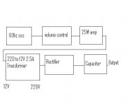
My first thought was to use a 1:1 mains transformer together with a bridge rectifier
followed by a simple RC filter, then a pot meter to adjust the rectified and filtered voltage.
But because I want to limit the max load current to 100mA, I was puzzled how to solve this and what components to use.
The application of the LM317 never crossed my mind.
Regards all..
Joe.
If regulated is not needed then a Variac with a suitable rectifier and caps at the output. Switchable fuses with different ratings for protection?
Of course I could use a variac but then it must be a type where the output separates from the mains.
This type is expensive (at least in my country) apart from its unhandy heavy weight .
Joe.
Motorola used to make a regulator chip that was ideal for lab power supplies, the MC1466. I'm pretty sure the app notes include an adjustable high voltage supply. There's a link to a recreation of it using discrete components in my post here http://www.diyaudio.com/forums/powe...0-5a-power-supply-schematics.html#post2266093.
The LM10CH app notes include a lab power supply regulator, and last time I checked that chip was still available.
The LM10CH app notes include a lab power supply regulator, and last time I checked that chip was still available.
Since you only need about 100ma you might be able to do something like this.
Looking at your proposal, is it not easier using a 1:1 main transformer (primary side connected to the mains),
then the rectifier and the capacitor and shunting this with for instance a 470k pot meter to obtain an adjustable voltage? The top side of the pot meter
is connected to the rectified voltage (about 250V).
And then there remains of course the problem how to draw a supply current of say 60mA.
Obviously this cannot be drawn via the slider of the pot meter, but perhaps some
(high voltage) NPN emitter follower will do the trick.
Last edited:
True, but with what I suggested you would not have to have a pass transistor dissipating 20W
when you are delivering 50V at 100 ma (250-50V*.1A). Not to mention safer as all your power control circuitry would be low voltage. The parts count would definitely be higher though.
when you are delivering 50V at 100 ma (250-50V*.1A). Not to mention safer as all your power control circuitry would be low voltage. The parts count would definitely be higher though.
what about using tubes after all jogris has some nice schematics available .
Verschiedene Roehren-Netzteile und ihre Schaltungen
for the amperage your needing a transformer from an old tube radio is enough
http://www.jogis-roehrenbude.de/Roehren-Geschichtliches/Roehren-Netzteile/EL86-Netzteile.pdf
tubes are cheap PL84 is identical to el86 and will supply about 60 milliampere take another tube and some zener diodes and incorperate an error amplifier
the materials are easy to acquire if your having trouble i might be of assistance
one thing to note is that a solid state solution is gone in a snap while a tube will put up a considerable fight .
This regulator can be adapted by making R2 variable between ~100K and 500K.Hello,
This is the first time I am posting on this Forum, so have a little bit kindness please.
I am trying to build a regulated voltage supply with the range of 50–200 Volts and a maximum capability of a 100mA load. But without having to use tubes.
Yes, I can browse this whole part of the Forum to see if there is already published something, but anyway…..
Can somebody help me please?
Joe.
Performances are pretty mean, but since you need no regulation, that should be sufficient.
Attachments
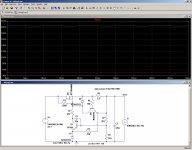
This regulator can be adapted by making R2 variable between ~100K and 500K.
Performances are pretty mean, but since you need no regulation, that should be sufficient.
Thank you very much Elvee for this circuit diagram.
At first glance I suppose the Mosfet M1 is the current limiting part of the circuit?
If the current though R5 exceeds a certain value then collector current of Q2
flows through R1 which starts to decrease the Vgs voltage of M1 increasing the
‘on’ resistance of the Mosfet. Hope this is correct?
I will analyse this circuit using LTspice (which you did also I see) to get more insight.
Joe.
M1 is the ballast element, it does the voltage regulation, and optionally the current limiting, under the control of Q2.
If current limiting is not required, you can drop Q2-R5-R6.
You can also create a foldback mechanism, to reduce the dissipation when limiting, by tying a resistor between Q2's base and M1's drain.
See the thread "Simple HV series regulator" for an example.
I do not have a copy of the .asc file on this computer, tonight I'll be able to post it (it is not complicated anyway).
- Status
- This old topic is closed. If you want to reopen this topic, contact a moderator using the "Report Post" button.
- Home
- Amplifiers
- Power Supplies
- 50-200V regulated power supply