Hi all,
I have designed and built a 500W peak offline SMPS for audio use that I wanted to share on this forum.
I use it with a Class-D amplifier based on IRS2092 that I designed and everything works fine.
The SMPS is designed to deliver +/-50V at 2A continuous (for thermal reasons)
and a peak of 5.5A par rail (550W peak power).
It provides also a ground referenced auxiliary output at around 18V useful to
power protection circuits.
The SMPS is based on the Transition mode 2-switch flyback topology with L6565 PWM IC and pulse transformer drive.
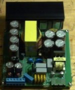
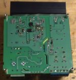
In attached you will find the schematics and some pictures of it.
Here are the measured characteristics:
Input range: 187...265VAC
Efficiency @ 5.5A out = 92.5%
Efficiency @ 2A out = 93%
Standby power < 3W
Peak output current: 5.7A
Short circuit current: 18A for 300ms (hiccup cycle)
Output ripple < 200mVpp @ 5.5A out.
Magnetics parts:
Transformer: EER42/20 Core with ~1.5mm gap on the center leg
primary: 32turns 4x0.45mm (split in 2 16 turns layers)
secondary: 9 turns 8x0.45mm per section
bias: 3 turns 1x0.45mm
aux: 3 turns 1x0.45mm
primary inductance: 250uH
leakage inductance: 3uH
Pulse transformer: high permeability toroid core diameter 15mm
pri=sec1=sec2=20turns wrap wire, trifilar wound
EMI filter: stolen from a PC power supply... measured 2x15mH
Any questions or comments are appreciated
thank you
ciao
-marco
I have designed and built a 500W peak offline SMPS for audio use that I wanted to share on this forum.
I use it with a Class-D amplifier based on IRS2092 that I designed and everything works fine.
The SMPS is designed to deliver +/-50V at 2A continuous (for thermal reasons)
and a peak of 5.5A par rail (550W peak power).
It provides also a ground referenced auxiliary output at around 18V useful to
power protection circuits.
The SMPS is based on the Transition mode 2-switch flyback topology with L6565 PWM IC and pulse transformer drive.
In attached you will find the schematics and some pictures of it.
Here are the measured characteristics:
Input range: 187...265VAC
Efficiency @ 5.5A out = 92.5%
Efficiency @ 2A out = 93%
Standby power < 3W
Peak output current: 5.7A
Short circuit current: 18A for 300ms (hiccup cycle)
Output ripple < 200mVpp @ 5.5A out.
Magnetics parts:
Transformer: EER42/20 Core with ~1.5mm gap on the center leg
primary: 32turns 4x0.45mm (split in 2 16 turns layers)
secondary: 9 turns 8x0.45mm per section
bias: 3 turns 1x0.45mm
aux: 3 turns 1x0.45mm
primary inductance: 250uH
leakage inductance: 3uH
Pulse transformer: high permeability toroid core diameter 15mm
pri=sec1=sec2=20turns wrap wire, trifilar wound
EMI filter: stolen from a PC power supply... measured 2x15mH
Any questions or comments are appreciated
thank you
ciao
-marco
Attachments
Nicely done. I've used the "DC Restore" diode in the gate drive secondary in some of my own designs and it does have one drawback. When the pwm is inhibited, by UVLO for example, the primary coupling cap can ring with the drive xfmr enough to turn on the main FETs. Maybe not all the time and maybe the energy in the bulk caps won't blow out the FETs right away, but it's still dangerous. I've seen it happen. What I've done is to minimize the values of the coupling caps and add damping. In 100KHz designs, I'd use a 0.1uF||(0.47uF + 50 Ohms) on the primary and 0.033uF||1K on the secondary.
YES, Pwrmad is right.......the DC restore prafo gate drive circuit is HIGHLY SUSPECT.........
http://www.edaboard.com/thread231931.html
I am afraid that this DC restore circuit must be decalred dangerous and a threat to the lifetime of the product.
http://www.edaboard.com/thread231931.html
I am afraid that this DC restore circuit must be decalred dangerous and a threat to the lifetime of the product.
Also, may i also say....
1...You need a PNP turn off circuit on your upper fet.
2....Why bother with the lower gate drive secondary....just drive the lower fet directly from the L6565 output.
3.....What is your peak and RMS current in fets and output diodes?.....i believe it will be ridiculously high when at 500W load.
....i think you need a continuous mode flyback......if you make it continuous above , say , 200W, it will be discontinuous at lower powers and thats fine for you.
4......have you multiple sandwiched your seconday.....otherwise each half of the output coil will not "see" similar coupling intothe core, and you will not get symetrical rails.
5.....npn/pnp gate drives are a bad idea, because the tolerance on such discretes is poor....and you cannot gaurantee enough hfe at high-ish Ic values.....also, the fT values willl be poorly toleranced..........you should use a proper gate driver IC instead.
6.........your primary fets and secondary diodes are on the same heatsink...so how have you got sufficient isolation between them.
7......your high primary bus capacitance is going to nuisance trip your fuse too often......the fuse manufacturer will tell you this wont happen...but it will.
8......When low bass notes are played, your split rails will loose symetry.....you need to solve this by doing an smps for each split rail... or at the very least, used weighted feedback from SGND and VREC+
9....C23 and C24 will cause you grief, they will resonate like mad with the leakage inductance when the fets are switched off.
10...R30 is the wrong side of C31
11....You forgot to connect SGND between C20 and C18
12....i think the use of Q5 is erroneous.
13...you have big heatsink for fets and diodes...but why then no heetsink for mains rectifier bridge.
14.....you need active power limiting circuit...becauuse your smps will go up in smoke if on 500W continuously...unless you can proove that under no circumstance will it see 500W continuous.
cheers
All the best
Hi,
Also what speakers are you driving with that output...it must be several speakers in series?
also..is your start up circuit capable of supplying full operating current...if so , then you have insufficient short circuit protection.
...
ALSO....your SMPS will BLOW UP, because you are reflecting more than 300V to the primary, and at low vin, when the input caps are at the trough, there will be less than 300V there, so you will have big problem....I am sorry, it was great of you to present........i also always make big big mistake, and then some other tells me about it and i am sad.....but i must tell you my friend, so your DIY will be in future sucesful and you will be happy in the long term.
I wish you every future success, thanks for your interesting concept.
Last edited:
I didn't mean to suggest that the DC Restore should never be used, only that it needs to be implemented carefully. I've used it, with damping and minimized tank energy, in several successful designs. I do agree that PNP turn-off circuits would be a good idea, especially with these large FETs. Diodes Inc, make some very nice transistors for the gate drive. Tiny, yet fast and lots of current gain for high peak currents. They even have duals for this application. Dedicated gate drive ICs are good too, but not perfect. I would always drive both FETs identically, not one direct and one by xfmr. When both switch together, it minimizes common-mode voltage/current on the xfmr windings. Interleaving xfmr windings is almost always a good thing. My preferred build would be: half primary in one layer; secondary wound bifilar in no more than two layers; half primary in one layer; aux windings can go where convenient. Inrush limiting is always a good thing. C23/24 do need a damping resistor. 50-100 Ohms. Probably 2W.
thanks Pwrmad, i hear you say you use the circuit with success, but have you done long-time soak testing of it, to see if the lifetime of the smps is affected......(ie by the gate drive problem)
Those diodes.com or zetex transistors are very expensive, -if you are going to use them you might just as well spend the money on a gate drive chip.
With a two transistor forward or flyback it really doent matter if you just drive the bottom fet directly......no current will flow until both are on so who cares if the directly driven one comes on first....it really doesnt matter........and in any case, even of you drive both off a coil......then each coil will likely have different leakage, and come on at different times any way....not only that but the series resistance of the fet gates is likely to have tolerance, so we can forget the fets ever coming on at the same instant........its best to just use a simple single output gate drive transformer.
Hi,
I notice that you say you achieved 92.5% efficiency with this boundary conduction mode flyback when Vin was 187VAC, and the output power was 550W.
I am sorry, but i believe that this is an error in the measurement.....there's absolutely no way a BCM flyback at 550W from 187VAC can do 90%+ efficiency.
How did you measure your input power?
Also, your claim that efficiency at 200W output was just half a percent less than at 550W output is impossible to believe.
I think you have a serious measurment error here.
Last edited:
eem2am, I don't think I've ever actually seen a failure attributable to this issue. The potential was first shown to me by a colleague working with me on the same power supply about 15 years ago. We worked out the fix I outlined above. That power supply and others (probably 7 different converters) that used that circuit have undergone extensive development, qualification, production and life testing, including HALT testing, without incident linked to this issue. But, I have seen scope captures showing Vgs ringing to several volts and the bulk supply voltage crashing down when pwm is inhibited at turn-off and that's enough for me. The Zetex parts are not that expensive. For commercial product where pennies matter, maybe. For the DIYer not so much. The difference is minimal. You're right, the drive scheme doesn't really matter. I've almost always driven two-switch converters with identical xfmr circuits in the hope that it would allow symmetrical switching of the primary winding and minimize the common-mode current through the pri-sec capacitance. It's a design choice. I've never tested the difference because that would require building two versions of the unit when development schedules barely allow time to build and test one. The one time I did use xfmr drive on only the top switch in an offline 2-switch forward converter. It worked just fine.
Also, may i also say....
1...You need a PNP turn off circuit on your upper fet.
2....Why bother with the lower gate drive secondary....just drive the lower fet directly from the L6565 output.
3.....What is your peak and RMS current in fets and output diodes?.....i believe it will be ridiculously high when at 500W load.
....i think you need a continuous mode flyback......if you make it continuous above , say , 200W, it will be discontinuous at lower powers and thats fine for you.
4......have you multiple sandwiched your seconday.....otherwise each half of the output coil will not "see" similar coupling intothe core, and you will not get symetrical rails.
5.....npn/pnp gate drives are a bad idea, because the tolerance on such discretes is poor....and you cannot gaurantee enough hfe at high-ish Ic values.....also, the fT values willl be poorly toleranced..........you should use a proper gate driver IC instead.
6.........your primary fets and secondary diodes are on the same heatsink...so how have you got sufficient isolation between them.
7......your high primary bus capacitance is going to nuisance trip your fuse too often......the fuse manufacturer will tell you this wont happen...but it will.
8......When low bass notes are played, your split rails will loose symetry.....you need to solve this by doing an smps for each split rail... or at the very least, used weighted feedback from SGND and VREC+
9....C23 and C24 will cause you grief, they will resonate like mad with the leakage inductance when the fets are switched off.
10...R30 is the wrong side of C31
11....You forgot to connect SGND between C20 and C18
12....i think the use of Q5 is erroneous.
13...you have big heatsink for fets and diodes...but why then no heetsink for mains rectifier bridge.
14.....you need active power limiting circuit...becauuse your smps will go up in smoke if on 500W continuously...unless you can proove that under no circumstance will it see 500W continuous.
cheers
All the best
Hi all,
thank you for your comments.
1) PNP turn off: I had tried it but I don't need to turn off the fets very fast.
My gate discharge resistors are 6.8R and they give me reasonably good
gate and drain waveforms
2) I don't like this. Using a dual secondary GDT makes everything symmetric and when the fets turns off they share the reflected voltage quite evenly.
3) At 500W load 230VAC input
Ifet_peak:9.24A
Ifet_RMS:3.19A
Idiode_peak:16.42A
Idiode_RMS:8.29A
At 200W load 230VAC input
Ifet_peak:3.69A
Ifet_RMS:1.28A
Idiode_peak:6.57A
Idiode_RMS:3.04A
With L6565 you are always at the border between CCM and DCM. It is true that in DCM peak and RMS current are higher but you can deal with it using bigger fets and diodes. QR operation has the following advantages:
- The fets turns on at zero current and minimum voltage --> turn on losses
are minimized
- Diodes turns off at zero current --> recovery time losses are minimized
4) Transformer construction
---------- bias 3 turns -----------
---------- aux 3 turns ------------
-------- 1/2 pri 16 turns ----------
-------- 1/2 sec 1 5turns ---------
-------- 1/2 sec 2 4turns ---------
-------- 1/2 sec 1 4 turns --------
-------- 1/2 sec 2 5 turns --------
-------- 1/2 pri 16 turns ----------
oooooooooo bobbin ooooooooooooo
I hope this is clear. The windings are sanwiched and interleaved.
At 500W the rails are +49.5V / -50.5V
The best way will be to wind the two secondaries bifilar but I don't like it because at the exteremes there will be around 300V between the two secondaries that can easily break the enamel insulation and create a catastrophic failure.
5) I know that gate drive ICs performs better than BJTs totem poles.
However at those lowish power level I have always used this kind of
structure with no problems. Here you need a slow turn on and not a super
fast turn off. Anyway the main bottleneck in inreasing the gate drive
current is the GDT leakage inductance.
6) The heatsink is connected to protective earth. The fets and diodes are isolated with a silicon adhesive foil. There is always a minimum of 4.5mm of clearance distance between primary and earth and at least 2mm between secondary and earth. The distance between primary and secondary is >8mm.
Also the transformer is wound using 4mm margins on each side of the winding.
7) There is a 10R NTC for inrush current limiting. The measured peak inrush current is 35A, not enough to blow a T type 5A fuse. Things are different if the SMPS is powered with the NTC already hot....
8) This was one of my first questions: regulate only the positive rail wrt GND or regulate one rail wrt. the other leaving GND floating. It seems there are two school of tough each method with its advantages and disadvantages.
This SMPS will power a stereo class D amp with the channels running out of phase. I have done this to try to balance as much as possible the current consumpion from the rails.
9) C23 and C24 (and the fets Coss) resonate the magnetizing inductance
when the fets are turned off and after the current in the diodes is
decreased to zero. They are not snubbers and they don't need any R in
series. These two capacitors as well as the circuits around IC
pin 5 (ZCD) are tuned to turn of the fets exactly when the Vds is at its
minimum reducing switching losses. Of course these two resonates also
with the leakage inductance suddenly after fets turn off but:
- they are from an AC point of view in parallel with the fets Coss
- the total resonating capacitance is thus 2*Coss+C23+C24+Ctrafo.
- C23=100pF / C24=0 (NM) / Coss=450pF --> Ctot=1nF
- These 100pF are only to fine tune the resonant frequency being much
smaller 2*Coss
- This resonance with the leakage inductance is suddenly clamped by the
freewheeling diodes D4 and D6
10) you are right but since DZ4 is not mounted it is not important
11) no. GND is connected both on C20 and on C18
12) Q5 is used for overload / shortcircuit protection. As soon as the
rails loose the regulation the optocoupler is switched off. The IC supply
is cut thank to Q5 and the SMPS shuts down after C34 is discharged.
I have used this trick to avoid using the bias supply collapse to shut down
the PWM.
13) Right. At 500W continuous the bridge will blow. At 200W the temperature is ok. Anyway I have added a piece of aluminum foil to help the brigde
14) This SMPS supplies an amplifier intended for music reproduction.
It is almost impossible that it will deliver 500W continuous.
Anyway I have put two thermal breakeres one on the amp heatsink and
one on the SMPS heatsink that disconnectes the mains when the
temperature is >80°C
Gate drive DC restore: This was one of the problems I faced. When disconnecting the smps there was a peak that sometimes turned the fets on.
I have never had failures but I fixed the problem by reducing R10 and R15 to 1k (they were 10k).
Reflected voltage: of course you can not reflect more that the DC bus otherwise the freewheel diodes will blow.
My transformer turn ratio is 32:9 so my Vrefl is 50*32/9=178V
I have my UVLO set at around 210V so where is the problem?
Efficiency: measurentes are taken at 230VAC and not 187VAC. The input
power is measured with an AC wattmeter and the output is connected to an
electronic load. The SMPS is powered from a 1.5KVA variac. Efficiency when connected directly to the mains will drop down a little bit due to the fact
that the variac leakage indcutance improves the PF and reduced the input
RMS current somewhat.
ok but your secondary is +/-50V, thats 100V, so you are reflecting more than you say.
im sure you know efficiency must be tested at V(in) min.
Even if its music, if you are using components that cannot handle continuous max power then you must have exact time domain load power measurements before you begin......you cannot just say "oh its music so it'll be ok".......what will be the longest duration of maximum power, and how often will such durations repeat? etc etc.
These days , music doesnt always sound like "music", and you may be doing far more power than you think.
when your primary clamp diodes have finished conducting, the secondary diodes will start conducting, and if you view that secondary current, you will see it has big oscillations on it, making your diode RMS current even greater.
You won't get nice textbook triangle wave out of your secondary diodes.......not unless you use a lot of snubbing.....because you are peaking up to 16 Amps, and thats an enormous peak........
Hi eem2am,
thank for your comments.
i still don't agree with the reflected voltage. This about it as a dual output flyback with two 50v outputs. The reflected voltage will be 50*Npri/Nsec independent from the number of outputs.
If my reflected voltage was >300v I will blow my diodes as soon as I power it up and I will have no voltage at the output.
The reflected voltage divides in two equal parts (ideally) on the fets when they are off and each fet will see vds=(vbus-vref)/2 and this is confirmed in m vds waveforms.
Power rating: I understand what you are saying and you are perfectly right but I will use this smps and amp at home and not to power a pa system. Usually audio stuff are tested continuosly at 1/8 or 1/4 of they rated power so I think that a continuous rating of 200w for a peak power of 500w will be adeguate for my purpose.
Efficiency: sure that the worst case is at minumum input voltage but I measured it at typical voltage of 230vac.
Diode current: wrapping a Rogowsky coil around the diodes shows exacly what are you saying. The rms current is a little bit higher than the calculated one (assuming a triangle) but not a very big difference. To snub this I think that it is quite impossible without burning a lot of watts.
I don't consider 16A as an enormous peak... But this is just a matter of point of view.
I have desgined flybacks like this putting out 24v/40a with peak current in the rectifier (synchronous) of more than 90A... This is a huge peak for me....
Anyway thank you for your comments and suggestions.
Ciao
-marco
OK thanks Mag, but i do repeat that the reflected voltage impress's itself across the primary coil.
If it is bigger than the value at the dc bus then the two primary diodes conduct and bang.
remeber when you on big load, your primary dc bus goes down quite a lot....and then is when you may see the smoke.
I assure you that your +/-50V is just like a 100V one.......it seems that you think they are in parallel......but no i assure you, it would be no good to drive class D if in parallel.
Hi eem2am,
we all agree that if the reflected voltage is higher than the bus voltage the diodes will conduct and blow. But how is it possible, I continue to don't understand.
The positive rail is generated by the trafo winding from pins 8-10. This winding has 9 turns.
The negative rail comes from winding 9-10 and has also 9 turns.
The primary has 32 turns.
Now if I have +/-50v or 100v total if you prefer I can calculate the reflected voltage in the following ways giving the same result:
1) Vor=50*32/9=178v
2) Vor=100*32/(9+9)=178v
178v is for sure lower than my uvlo trip point and even without uvlo with all the capacitance I have on the primary I doubt that the DC bus will sag under 178v even at 187vac input.
It is a multioutput flyback converter giving two outputs of 50v/5a each. Or if you prefer they are in "parallel" as you are saying. When the primary is open the current starts to ramp down ond the secondary schottkys ideally with the same peak and rms current but with opposite direction. Check the phase of the transformer windings.
Thank you
OK sorry i mis-read your secondary turns...My Mistake.
By the way, do you not prefer Continuous mode with SiC output diodes?......lower RMS current.
I take it you have picked BCM for the transient response?
Mind you , i rekkon at the 500W level, you will see no more than 70% effciency with BCM.......So when on 500W, you will be dissipating about 210W.......So thats 210W mostly in your diodes, but also in fet and trafo.
So your diodes are going to be dissipating around 85W.
Are you sure theyre inside temperature maximum?
I rekkon you will need a fan....unless as you say your peak power durations really are very short......until eight bass guitarists plug their guitars into a multiplex box and then into your class d amplifier.......and then you really are on 500W continuously.....
....then again, also, have you looked into short circuit and overload protection
Hi,
now we agree on the reflected voltage.
Diodes: I use two mbr20200 schottky diodes. The peak inverse voltage is 155v with vin=265vac
200v allows me to use schottky diodes with lower vf compared to ultrafast diodes.
Sic diodes are 10 times more expensive than schottky and the vf is much higher.
There are no trr related problems in bcm I used schottky because of their lower vf, not for speed issues.
Efficiency:
As I said before the efficiency is measured at 230vac. Even if the variac makes things a little bit better due to partial PF correction I can be sure that the efficiency is >91%
i don't know from where your figures come from but i can assure you that 70% is impossible to achieve even if you do everything in the wrong way.
For this kind of power and pretty high output voltage the efficiency is for sure >85% even without great optimization. The power dissipated in the diodes is Pd=iout*vf+irms^2*rd, neglecting switching losses.
Now let's assume vf=0.85v and rd=20mohm for MBR20200. The power dissipated in each diode will be pd=0.85*5+8,2^2*0.02=5.6w per each diode, 11.2w in total, not 85w.
The real problem with bcm and dcm flybacks is the ripple current in the capacitors and this is especially true for high output currents, independent from power.
I know some design using bcm flyback for 24v/100A output performing reasonably well with >90% efficiency. The drawbacks are lots of electrolytics capacitors on the output and a transformer wich is made up from 3 stacked EE65 cores..... But it works well.
The standard guideline that says that flyback is good up to 100w or so it is imho surpassed. With modern power electronics devices and clever techniques designing a 500w flyback is not impossible and the problems to overcome are not worse than the ones you find in designing a forward type smps.
Well i have never tried flyback at 500W , so i dont know.
But with your findings, why is everybody using resonant converters for 500W now.....as you show 90+% for the flyback, we could all just use them.
I suppose you would tell that your flyback is a physically bigger solution size than "typical" topologies of that power?
Also, i know very well that you use no PFC. ...and that when you go on 500W the peak mains currents are very very very high....and they will nuisance trip your fuse at times.....the fuse manufacturer will tell you that this NEVER happens.....but oh yes it does...................if you ended up taking them to court for proven nuisance tripping, then they would just take you to court in return, and accuse you of doing SMPS without PFC for 500W.
Everyone knows we can all get away with non-PFC in audio at powers up to 600W.......but this is because the authorites turn a blind eye.......it is actually illegal.
Last edited:
resonant coverters like LLC are commonly used today for power up to around 1kw for the following
reasons:
- very high efficiency (you can achieve >93% PFC+LLC combined efficiency)
- very low EMI (the current is sinusoidal)
- small transformer size for a given power level
- very small requrement on output capacitors (there are some LED ballast working with no electrolytics caps at all, just some small film caps)
- no need for an output storage choke
but:
- input voltage range is quite limited, a PFC is mandatory for these topologies
- transient response: not as fast as a peak current mode controlled bcm flyback
- the transormer is difficult to design, the leakage inductance must be high and well controlled
requiring special bobbins not easy to find
_ for power from 1kw up to 4-5kw the best possible solution is the phase shift converter also here a PFC is mandatory for good performance
PFC: I know don't have PFC and everything above 75w needs it. Anyway I have designed this smps for personal use and I don't intend to pass any reguation approval. If I need to design something that must be sold for sure I will make it with active PFC.
In the industrial market there are plenty of smps of >1kw power with no PFC at all and nobody seems to take too much care about it....
Ciao
-marco
Thanks Mag:
I see i agree with you that LLC cannot handle a high input voltage range..but others assure me that it can......i cannot define exactly why the LLC needs a relatively constant Vin......after all, if you make the magnetising inductance relatively small, then the gain of the LLC stage becomes large and surely you can handle wide Vin variation?
Regarding transient response of LLC vs BCM current mode flyback.........i am told that the LLC converter can be done at much higher frequency than BCM flyback, so therefore it can actually have a faster transient response than BCM flyback.
Of course, i am sure you are aware that one does not need special bobbins for an LLC...you can implement the resonant inductor with a separate inductor, though i admit it may end up being physically quite large.
Regarding sold products being best to do with PFC......i agree with you, but companies like Fender etc dont use PFC in there 150W amplifiers....
Regarding above 1KW.....Companies that use that kind of power level usually have to actually pay for the apparent power that they draw.....so the government is getting money out of them so is not too bothered if they dont have good pfc....because they pay dearly for it.
Last edited:
- Status
- This old topic is closed. If you want to reopen this topic, contact a moderator using the "Report Post" button.
- Home
- Amplifiers
- Power Supplies
- 500W SMPS for audio