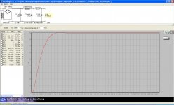
I have modeled a power supply in PSUD II that should produce about 9V, will be used to supply a voltage regulator that will output a steady 5V. The PSU model is attached.
The transformer is a Signal flatpack transformer 12.6V 200ma in series hookup (Digikey part#595-1313-ND )here Digi-Key - 595-1313-ND (Manufacturer - LP-12-200)
I used 12ohms for the DCR in the PSU model since the flatpack will be hooked up in series connection - does anyone know if that is correct for the flatpack series connection?
The 27A 600V IXYS FRED Bridge Rectifier is here http://www.partsconnexion.com/product4794.html
Will it work well for this power supply? I also used the LN4005 in the PSU model since it has a 600V PIV and seemed closest to the 600V IXYS FRED Bridge Rectifier, is that okay as well? Thanks in advance for any comments.
The values for the parts in the model are
T1=12.6V 12ohms DCR
Bridge=LN4005
C1=4uF 1ohm
L1=300mH 5ohms
C2=940uF 1 ohm
R1=9.1 ohm
C3=2mF 1 ohm
I1=50mA
Attachments
Last edited:
That's sheer madness: the bridge is more than 100x too large.The 27A 600V IXYS FRED Bridge Rectifier is here http://www.partsconnexion.com/product4794.html
Will it work well for this power supply? Thanks in advance for any comments.
Overdesign to such an extent can only be counter-productive.
Why do you have 1ohm resistance for all capacitors? That is extremely poor. Are they from a specialist "audiophile" series?The values for the parts in the model are
T1=12.6V 12ohms DCR
Bridge=LN4005
C1=4uF 1ohm
L1=300mH 5ohms
C2=940uF 1 ohm
R1=9.1 ohm
C3=2mF 1 ohm
I1=50mA
I wouldn"t use that transformer ..... if you use it at 12.6v AC that will give you about 17V DC so you will have to drop 12v DC in the regulator which depending on the current draw can mean a lot of heat for the regulator to dissapate ......
If you use it at 6.3v AC you might not have enough voltage overhead for the regulator ....6.3v X 1.41V=8.8v - 1.5v diode drop =7.3 - 5v=2.3v overhead for the regulator , that might be enough depending on the regulator but it doesn"t leave any voltage left if the mains voltage fluctuates .....
I would look for one that does 8v AC or 9v AC ...... Or you can find a 9v DC wallmart power adapter and open it up and take the transformer out and use that which would give you 9v DC which means the Regulator will have enough overhead and will only have to drop 4v and you can probably find one for a buck at the thrift store .....
I would look for one that does 8v AC or 9v AC ...... Or you can find a 9v DC wallmart power adapter and open it up and take the transformer out and use that which would give you 9v DC which means the Regulator will have enough overhead and will only have to drop 4v and you can probably find one for a buck at the thrift store .....
Or just use the power adaptors 9VAC straight and that will be safer than having mains in your enclosure.
Hi James dB,
I have no idea what is the answer to your question. However, I was delighted to find your mention of PSU Desinger! I've been designing and building my first linear unregulated PS using the free student edition of SPICE . I thought "wouldn't it be great if someone made a design program specifically for linear, unregulated power supplies?" But I figured, no one is going to bother with that. And here it is! in your post!
It just goes to show the advantage of wandering aimlessly through interesting-looking posts.
Good luck with your build James, and I hope you find the answer to your question, whatever it is.
I have no idea what is the answer to your question. However, I was delighted to find your mention of PSU Desinger! I've been designing and building my first linear unregulated PS using the free student edition of SPICE
. I thought "wouldn't it be great if someone made a design program specifically for linear, unregulated power supplies?" But I figured, no one is going to bother with that. And here it is! in your post!It just goes to show the advantage of wandering aimlessly through interesting-looking posts.
Good luck with your build James, and I hope you find the answer to your question, whatever it is.
report states:
simulate for 900ms after a reporting delay of 0s.
This deals with start up and shortly thereafter.
Change that line to 100ms after 1000ms (1s)
and look at what your various voltages and currents are doing in the continuous mode.
BTW,
you have created and modeled an rCLCRC filter. Mains hum on the output should be very low.
Most of the performance will be controlled by the last C. That's where you put the money in high quality audio applications.
Last edited:
Elvee, I used 1ohm for caps as they are small and the PSUD default starts with a 100ohm cap at 2 ohms. Many websites do not show the resistance for caps on sale so thats just a guess. I have the particular bridge on hand, but Imay be better off buying some individual diodes having more suitable ratings, and making a bridge, thanks.
What are your ripple goals? It seems you are going to a lot of trouble for a very basic circuit, if all the CLCRC filtering is needed it is probably only because you used a poor regulator IC.
With a 50mA current requirement you can get away with using many regulators. Parallel secondary for the transformer is about 6.3VAC turned into 7.6V. A 2.6V margin above 5.0V output should be fine for 50mA current using a typical LM7805, LM317, etc., let alone low dropout regulators if you don't have the L & R before the regulator. For example with LM317, at 50mA and 50C operating temperature, dropout is around 1.5V. Yes AC mains variations could give less margin but the mains shouldn't be changing that much.
However, you could go the other route and use 12VAC in from series secondary transformer windings and have 16VDC to regulator, since with only 50mA current that's only 0.05A * 11V drop = 0.6W heat dissipation. You won't win any efficiency awards but it is only half a watt meaning you don't even need a heatsink on a TO220 sized regulator in typical room temperature environments.
So, I'm suggesting all you probably need is the transformer, some cheap 1N4001 or better diode bridge, a 330uF+ capacitor, 0.1uF film or ceramic capacitor before the regulator, typical LM317 datasheet components to reach 5V out. Filtering before a regulator isn't all that important unless you have a lot of high frequency noise then a couple ferrite beads on the regulator input and output leads might help. I mean within the assumption that you at least have enough capacitance that the supply voltage prior to the regulator never drops below the minimum threshold (1.5V above 5V output @ 50mA/50C) in the case of LM317 mentioned above).
Last edited:
Your 4µ is most likely some plastic type, meaning it will have a resistance in the 0.1Ω range or less, and the e-lytics will normally have some tens of millohm.Elvee, I used 1ohm for caps as they are small and the PSUD default starts with a 100ohm cap at 2 ohms. Many websites do not show the resistance for caps on sale so thats just a guess. I have the particular bridge on hand, but Imay be better off buying some individual diodes having more suitable ratings, and making a bridge, thanks.

^ but no need for a bridge either, 4 x 1N4001 diodes are only a few pennies. Then again, 1N4004 aren't much more expensive either.
However, either the diodes (or usually the bridge rectifier) are silicon diodes with a forward voltage drop so instead of 9V, regulator input would be closer to 7.5V if using the 6.3VAC transformer secondary. Doesn't necessarily matter though, I mentioned LM317 can handle that and LM7805 can too though LM7805 leaves a little more ripple.
However, either the diodes (or usually the bridge rectifier) are silicon diodes with a forward voltage drop so instead of 9V, regulator input would be closer to 7.5V if using the 6.3VAC transformer secondary. Doesn't necessarily matter though, I mentioned LM317 can handle that and LM7805 can too though LM7805 leaves a little more ripple.
Last edited:
6Vac 500mAac is only 3VA.
The regulation of a transformer this size is likely to be around 30%.
The max continuous DC from the smoothed rectifier output is 250mA.
50mA is just 20% of max continuous.
Expect the effective Vac to be ~6+15% for a 50mAdc output.
That will give around 8.2Vdc to 8.5Vdc +- hum ripple.
5Vdc @ 50mAdc should be very possible for a range of mains voltage of +-6% on a 230:6Vac 500mAac transformer and regulated PSU.
- Status
- This old topic is closed. If you want to reopen this topic, contact a moderator using the "Report Post" button.
- Home
- Amplifiers
- Power Supplies
- PSU Model for a 9V PSU, parts question