Hi all,
I am using the attached design but the lm317 blows out without any reason I can identify - I already blew 6 of them. And yesterday I blew lm337
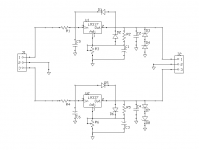
Input is +38V 0 -38V and output is adjusted to +16V 0 -16V. It is used to power a few opmaps so current is low. The capacitors are 100uf and the zener dioes are 8.2V and I put them to protect against high voltage at the output.
Any idea what's the problem?
Thanks,
Eli
I am using the attached design but the lm317 blows out without any reason I can identify - I already blew 6 of them. And yesterday I blew lm337
Input is +38V 0 -38V and output is adjusted to +16V 0 -16V. It is used to power a few opmaps so current is low. The capacitors are 100uf and the zener dioes are 8.2V and I put them to protect against high voltage at the output.
Any idea what's the problem?
Thanks,
Eli
Attachments
the lm317 blows out without any reason I can identify
Are you absolutely, completely, totally and without doubt sure that you are wiring them correctly?
?
?
?
If they are in properly, then take the zeners out and see if that makes a difference.
Are you sure the input voltage is not exceeding 38 volts?
There are a couple of cases where the absolute input voltage matters a LOT.
-1- on startup. Depending on your reference pin bypass cap, this will take a while to charge, the length of time determined by the resistors you have used from output to reference pin.
During this time the LM317 sees pretty much the full input voltage.
-2- if you short or overtemp the lm317, not unlikely if you are playing with a circuit.
In this case the lm317 will go into protective shutdown - and the delta V between in and out is the full input voltage.
I don't have the datasheet with me, but if I recall the
Max input - output delta V is 37 volts.
Check this, as these devices are usually pretty tough.
Oh and a third subtle failure $ode (though not too likely in your case) is where the positive and negative outputs get shorted. In this case the first regulator to go into over current shutdown has its output pulled to THE OPPOSITE rail. Putting reverse diodes across the output protects against this. Your zeners will likely save you in this case.
Think the above post covers most things.
Have the zeners ever failed or has one failed open circuit and you don't know it? I would replace those with just a single reversed diode on each output, say a 1n4004
Are there any electrolytics connected rail to rail on the circuit it supplies rather then rail to ground ?
Have the zeners ever failed or has one failed open circuit and you don't know it? I would replace those with just a single reversed diode on each output, say a 1n4004
Are there any electrolytics connected rail to rail on the circuit it supplies rather then rail to ground ?
Huh? What high voltage?zener dioes are 8.2V and I put them to protect against high voltage at the output.
You've made history in my book, blowing a half dozen of these chips.
Are you sure you are blowing the chips? They have overload protection and shut themselves down. Thinking about it... I'd bet you aren't blowing them, you just think you are. Might that be correct?
edit: I don't think your resistor values are correct.
Vout = 1+(R3/R1)+0.1 = 1+(2k/150)+0.1
You'll have to show me how you got 16 volts from that, or show me where I'm screwing up.
PS: and let's dispense with that 0.1 volt error term from the 50uA adjust pin
Last edited:
sofaspud: you forgot to multiply the ration in 1.2V to get around the required values.
as for your assumption I did not actually blow them -- could be. I ruled that out since after that happened, I let the circuit rest for some time before connecting power again and got the same results but I could be wrong.
as for your assumption I did not actually blow them -- could be. I ruled that out since after that happened, I let the circuit rest for some time before connecting power again and got the same results but I could be wrong.
OK thanks. Yep I screwed up.
And you're convincing that you did indeed blow the vregs.
That gets me very curious! I still don't understand the zeners, though. To me (OK that ain't saying much) they kind of seem redundant with D1 & D5 included.
You mention a possibility of a short on your PCB. I could see shorting the output and adj pins causing havoc, but if a negative vreg has blown too that tends to rule that sort of thing out. But some type of short seems likely if R1 is getting hot. You could try getting some resistance measurements, especially if the vreg is out of the circuit.
If C1 is 100uF, I think the datasheet suggests something like 10uF. googlyone may be on to something there.
Last edited:
OK thanks. Yep I screwed up.
That gets me very curious! I still don't understand the zeners, though.
I once saw the voltage at the output become identical to that of the output so I added the zeners to protect the opamps (luckily my preamps circuits were not connected than
Are you sure the input voltage is not exceeding 38 volts?
There are a couple of cases where the absolute input voltage matters a LOT.
-1- on startup. Depending on your reference pin bypass cap, this will take a while to charge, the length of time determined by the resistors you have used from output to reference pin.
During this time the LM317 sees pretty much the full input voltage.
I see... maybe I bought lousy cheaps that do not provide what the spec promises...
-2- if you short or overtemp the lm317, not unlikely if you are playing with a circuit.
In this case the lm317 will go into protective shutdown - and the delta V between in and out is the full input voltage.
I don't have the datasheet with me, but if I recall the
Max input - output delta V is 37 volts.
The spec says vout-vin <= 40V so it should be OK
Check this, as these devices are usually pretty tough.
Oh and a third subtle failure $ode (though not too likely in your case) is where the positive and negative outputs get shorted. In this case the first regulator to go into over current shutdown has its output pulled to THE OPPOSITE rail. Putting reverse diodes across the output protects against this. Your zeners will likely save you in this case.
The LM317 and 337 have different pinout!
Please check the datasheet for LM317/LM337 for details
This is dead right.
If you build the circuit with components connected as shown, the -ve regulator will have the input and output pins swapped.
I strongly recommend that you check your schematic and PCB. This is not a big job, and something you need to do. These IC's are ridiculously reliable, so bottom line is there is an oops in there somewhere.
If your schematic is correct and the PCB footprint you are using is the same for the LM317 / 337 then you will need to turn the Lm337 around.
If the LM337 is in back to front, it will not be happy, and could cause a number of interesting secondary failures. With 38Volt supplies things could get messy.
PS: I still remain somewhat concerned about the 38 volt input. If this is from an unregulated supply there is real opportunity for peaks to go too high. With the LM7815/7915 I have experienced spectacular failure of these when operated from rails that exceed their maximum rating by very little. Mind you this was 25 years ago!
I am aware of the different pinout of lm317 and lm337. And I have seen both voltages working and adjustable so I assume no errors in wiring. The imput voltage comes from a transformer, rectified and with generous capacitors - 2x18000 uF. My overall project is a 2xguitar inputs + tone control, 4 microphone inputs all mixed together.This is dead right.
If you build the circuit with components connected as shown, the -ve regulator will have the input and output pins swapped.
I strongly recommend that you check your schematic and PCB. This is not a big job, and something you need to do. These IC's are ridiculously reliable, so bottom line is there is an oops in there somewhere.
If your schematic is correct and the PCB footprint you are using is the same for the LM317 / 337 then you will need to turn the Lm337 around.
If the LM337 is in back to front, it will not be happy, and could cause a number of interesting secondary failures. With 38Volt supplies things could get messy.
PS: I still remain somewhat concerned about the 38 volt input. If this is from an unregulated supply there is real opportunity for peaks to go too high. With the LM7815/7915 I have experienced spectacular failure of these when operated from rails that exceed their maximum rating by very little. Mind you this was 25 years ago!
- Status
- This old topic is closed. If you want to reopen this topic, contact a moderator using the "Report Post" button.
- Home
- Amplifiers
- Power Supplies
- having hard time with lm317/337