Sorry for thatand i am waiting for you to give the core dimensions, core area is you can please....hard to tell from the photos....
i do not give credence to any label on the traffo alone.......
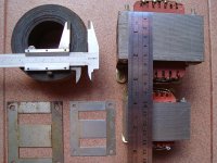
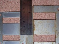
 , this is the core area size
no1 = 2.5cm * 4.5cm = 11.25cm²
no2 = 3.2cm * 5.3cm = 16.96cm²
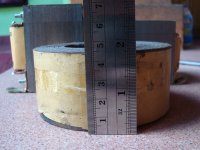
& toroid = 2cm * 4.5cm = 9cm²
Attachments
low B = bellow 1T?A low B transformer will stay cool, but also stray fields will be minimal (two coil c-core transformers have already an advantage over EI), and the transformer will be more quiet; all these factors are somehow interrelated.
I don't know how it looks of that C-core trafo,
do you have the picture of that kind of trafo?
what its size & VA ratting too
I just wanna know
")
After recalculate I realize all my question has been answeredThanks to all reply,
now I can recalculate every things, every thinks too


So here the formula + new formula:
for 50 Hz operation
@ B = 1T & E I core
N = 45 * U / A
@ B = 1.6T & toroidal core
N = 28.125 * U / A
for 60Hz operation
@ B = 1T & E I core
N = 37.5 * U / A
@ B = 1.6T & toroidal core
N = 23.4375 * U /A
Thanks for this formula
B = 50/f x 45 / (A x N) x U
f = frequency in Hz
U = rms value of voltage in V
A = magnetic core cross-section in cm²
B = flux density amplitude in T(tesla)
N = number of turns
Note : B can be vary from what material we use to make transformer
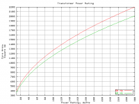
Then for the VA ratting we can see from those attachment
also from RDH3 VA = (5.58 * A)² or write like this VA = (5.58 * A) * (5.58 * A)
I hope No mistake from all that formula that I make
So next step is make it !!!
Thanks for all
Andrew T.
Tony
KatieandDad
pieter t
alexcp
zigzagflux
johansen
GBU
PEACE
Andrew T.
Tony
KatieandDad
pieter t
alexcp
zigzagflux
johansen
GBU
PEACE
Attachments
Last edited:
You can check the primary winding before you add on the secondary winding/s
Use a Variac to supply 0Vac to {maximum+5% of mains voltage} to the primary winding.
At each Primary Voltage measure the Primary Current. Be very careful, you are working with Mains Voltage. no pets, no children, no nagging wife. A helpful over the shoulder supervisor is useful.
Plot Primary current against Primary voltage. You should get an S curve. The bottom part of the S should straighten up at a quite low Primary voltage, maybe of the order of 10Vac to 20Vac.
The top part of the S (where Primary Current increases disproportionately with small increase in Primary Voltage) should occur as you reach maximum test voltage.
If the curve starts asymptotically approaching horizontal at well below the normal mains primary voltage, then from what I read and have tested you have too few turns on the primary winding. Now is the time to modify the Primary Ampere Turns.
I have repeatedly asked this question in transformer threads, but none of the "experts" have given a clear or even any answer !
Not build anything yet ...
hope I have some more extra time,
to made
cool 300VA EI transformer,
but only use what I have here
I will post pictures & step by step, when I'm done
This one is trafo I have been made earlier
ImageShack® - Online Photo and Video Hosting
& this was how I winding the primary with double & same wire
to form input AC 110V in * 2 because easier to wind this way
but for safety it is not so good, better to use single 220V input
with good isolated per winding's layer
ImageShack® - Online Photo and Video Hosting
I guest its 500VA but its only 300VA .
Thanks
GBU & PEACE
hope I have some more extra time,
to made
cool
300VA EI transformer, but only use what I have here
I will post pictures & step by step, when I'm done
This one is trafo I have been made earlier
ImageShack® - Online Photo and Video Hosting
& this was how I winding the primary with double & same wire
to form input AC 110V in * 2 because easier to wind this way
but for safety it is not so good, better to use single 220V input
with good isolated per winding's layer
ImageShack® - Online Photo and Video Hosting
I guest its 500VA but its only 300VA .
Thanks
GBU & PEACE
Attachments
Last edited:
hi john
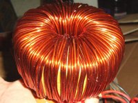
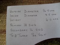
greetings sorry for not replying as i was out yesterday...this is my core and winding details...just want to know roughly power of toroidal as i have no idea what it's power is because a transformer 50 0 50 AC had burnt out and came for repairs we just counted the turns and SWG of wire and this is what data i used to wind my toroidal transformer by hand..need your help
Warm Regards
Andrew Lebon
Attachments
hi john
greetings sorry for not replying as i was out yesterday...this is my core and winding details...just want to know roughly power of toroidal as i have no idea what it's power is because a transformer 50 0 50 AC had burnt out and came for repairs we just counted the turns and SWG of wire and this is what data i used to wind my toroidal transformer by hand..need your help
Warm Regards
Andrew Lebon
I will try to answer ...
For primary no 18 SWG (see attachment, on table's right side, to get diameter in mm [* 25.4])
diameter is 0.0480 inch = 1.2192 mm (please measure your wire's diameter for sure)
wire area = 3.14 / 4 * (diameter)²
----------= 0.785 * (1.2192 * 1.2192)
----------= 1.167 mm²
max amps for S = 2.82A/mm² ---> 1.167 * 2.82 = 3.29A
max amps for S = 5A/mm² ------> 1.167 * 5 = 5.83A
so V/A ratting for 220 volt input = 724VA & 1287VA
there are 2 V/A ratting
724 is safe rating, if we draw 724VA, the trafo will be quiet cool
1287 is max rating, we can draw 1287 but the trafo will be hot
for secondary no 16 SWG
diameter is 0.0640 inch = 1.6256 mm
wire area = 2.074 mm²
max amps for S = 2.82A/mm² ---> 2.074 * 2.82 = 5.84A
max amps for S = 5A/mm² -------> 2.074 * 5 = 10.37A
V/A ratting for 100volt(50-0-50) output = 584VA & 1037VA max
I guess its good to keep VA rating of secondary less than primary, but please correct if I wrong.
I'm not trafo expert
Okay, now we enter the data to my formula...
but I don't know your mains voltage
your core area A = (16.5 - 7.5) * 4 = 36cm²
for 220volt 50Hz & toroid core
N = 28.125 * U / A
= 28.125 * 220 / 36
= 172 turns
for 220volt 60Hz
N = 23.4375 * U /A
= 23.4375 * 220 / 36
= 143 turns
Now we can see there is so big difference...
my formula say 172/220 = 0.78 turn per volt
but your data is 2 turns per volt
Where do this data come from? Is this core was a working trafo but somehow it melt down?
This really make me confuse, anybody help?
note: my toroid that I built based on "Automatic AC Voltage Regulator (Stavolt)" with same core size.
I open & calculate turn per volt of that stavolt to make my own toroidal trafo, then I calculate with my formula and the results are similar.
I also have one 2000VA(mark on the box) toroidal auto-transformer, not check data inside yet.
Now I'm also need any help, any reference will be welcome
Regards
Attachments

Hi John,
I have checked the top half of your post, down to
You ask about output VA and input VA.
I suggest you assume an efficiency for the transformer.
Let's say it's 95%. The maximum total output from all the secondary windings (based on the 2.82A/sqmm) will be 0.95 * 724 = 688VA.
Your 50+50 16swg @ 5.84Aac uses up 584 of those available secondary VAs. You have 104VA spare.
You can add extra turns to use that up. Or add extra windings to use that up. Or you can estimate the worst case VA loading conditions for a range of mixed voltage and current windings and pick out the worst operating condition and set that to use the whole 688VA available from the secondary.
Let's suppose you have some continuous current windings using 200VA and some ClassAB windings that normally run at 150VA but will increase to 700VA when testing to maximum output power. The total maximum load on the secondary will be 900VA while testing.
You can make a design design based on experience and measurement of how the transformer will operate when delivering half maximum power for 90% duty and full maximum power for 10% duty.
The effective total power is very approximately 200VA + 0.9*50%maxP VA + 0.1* 100% maxP VA.
We already know the 100% maxP VA = 700VA as above.
Let's assume the 50% maxP VA is >350VA try 450VA.
the likely worst case secondary VA is ~~~ 200 + 0.9*450 + 0.1*700 = 675VA. Just below the guesstimated 95% efficiency prediction.
You as designer can now build the transformer and the amplifier and test/measure it's performance. Since this is a new test of a new prototype you embed a few thermocouples in the core and primary winding and secondary windings and monitor operating temperatures for the worst case "real operating" conditions. When you are satisfied that your prototype is behaving as predicted or you have altered your model to fit with your test measurements then you can start production of your amplifier.
We as one or two off prototype builders don't do that thorough design exercise. We use our and others' experience to guide us to a reasonable set of estimates that give us reasonable model from which we make our predictions.
There is nothing wrong with having 5kVA of secondary windings on a 1kVA transformer, if you the builder/user know that you can never overheat the transformer with your intended usage nor exceed it's safety ratings during your worst case senarios.
Some ways of helping to ensure you don't inadvertently miss-use your amplifier and/or transformer is to fit fuses that blow if the target/modeled operating conditions are exceeded.
Close rated fusing is just one example. Output IV limiters are another. Heatsink temperature sensors/switches. It's a long list.
I have read and re-read your second part of the post.
I think your 0.78T/V is correct.
I don't know where 2T/V comes from either.
But I suspect the difference is something to do with you using
BEFORE, one applies a chart, or nomogram, or other empirical data to a design situation one must ensure that the conditions are appropriate. If no conditions are specified, be it on your own head when it bites you !!!!
I have checked the top half of your post, down to
Everything you have shown is correct so far.I'm not trafo expert
You ask about output VA and input VA.
I suggest you assume an efficiency for the transformer.
Let's say it's 95%. The maximum total output from all the secondary windings (based on the 2.82A/sqmm) will be 0.95 * 724 = 688VA.
Your 50+50 16swg @ 5.84Aac uses up 584 of those available secondary VAs. You have 104VA spare.
You can add extra turns to use that up. Or add extra windings to use that up. Or you can estimate the worst case VA loading conditions for a range of mixed voltage and current windings and pick out the worst operating condition and set that to use the whole 688VA available from the secondary.
Let's suppose you have some continuous current windings using 200VA and some ClassAB windings that normally run at 150VA but will increase to 700VA when testing to maximum output power. The total maximum load on the secondary will be 900VA while testing.
You can make a design design based on experience and measurement of how the transformer will operate when delivering half maximum power for 90% duty and full maximum power for 10% duty.
The effective total power is very approximately 200VA + 0.9*50%maxP VA + 0.1* 100% maxP VA.
We already know the 100% maxP VA = 700VA as above.
Let's assume the 50% maxP VA is >350VA try 450VA.
the likely worst case secondary VA is ~~~ 200 + 0.9*450 + 0.1*700 = 675VA. Just below the guesstimated 95% efficiency prediction.
You as designer can now build the transformer and the amplifier and test/measure it's performance. Since this is a new test of a new prototype you embed a few thermocouples in the core and primary winding and secondary windings and monitor operating temperatures for the worst case "real operating" conditions. When you are satisfied that your prototype is behaving as predicted or you have altered your model to fit with your test measurements then you can start production of your amplifier.
We as one or two off prototype builders don't do that thorough design exercise. We use our and others' experience to guide us to a reasonable set of estimates that give us reasonable model from which we make our predictions.
There is nothing wrong with having 5kVA of secondary windings on a 1kVA transformer, if you the builder/user know that you can never overheat the transformer with your intended usage nor exceed it's safety ratings during your worst case senarios.
Some ways of helping to ensure you don't inadvertently miss-use your amplifier and/or transformer is to fit fuses that blow if the target/modeled operating conditions are exceeded.
Close rated fusing is just one example. Output IV limiters are another. Heatsink temperature sensors/switches. It's a long list.
I have read and re-read your second part of the post.
I think your 0.78T/V is correct.
I don't know where 2T/V comes from either.
But I suspect the difference is something to do with you using
and 2T/V using a different constant for a different steel. But a data chart that does not specify the conditions with which it is compatible is worse than useless. It is potentially dangerous.N = 28.125 * U / A
BEFORE, one applies a chart, or nomogram, or other empirical data to a design situation one must ensure that the conditions are appropriate. If no conditions are specified, be it on your own head when it bites you !!!!
Last edited:
Why so much detail?
If this thread were only for sizing secondaries I would be relatively lax and use as built measurements to check my models for secondary voltages off load and on load.
BUT
This thread is about the mains connected PRIMARY.
It is important that anyone and everyone reading this Thread appreciates the dangers involved.
A builder working with mains voltages MUST ALWAYs take appropriate measures to protect him/herself from danger and is responsible for others exposed to that equipment.
One must fully understand the dangers and the problem before one can make the informed decision that one is competent to work with Mains connected Primaries.
I have never wound a Primary.
I have wound many Secondaries. I am still here.
torridal turns
Hi John
greetings and thank you for reply and i want to confirm its 2 TURNS PER VOLT this torridal was wound by hand and many have been made and working
well here in india we give our specifications to winder and he winds it thank you once again
warm regards
andrew lebon
Hi John
greetings and thank you for reply and i want to confirm its 2 TURNS PER VOLT this torridal was wound by hand and many have been made and working
well here in india we give our specifications to winder and he winds it thank you once again
warm regards
andrew lebon
Thanks to Sir Andrew TBUT
This thread is about the mains connected PRIMARY.
It is important that anyone and everyone reading this Thread appreciates the dangers involved.
A builder working with mains voltages MUST ALWAYs take appropriate measures to protect him/herself from danger and is responsible for others exposed to that equipment.
One must fully understand the dangers and the problem before one can make the informed decision that one is competent to work with Mains connected Primaries.
I have never wound a Primary.
I have wound many Secondaries. I am still here.
Everyone must agree with this danger,
please take care of your own...
keep in our mind, SAFETY FIRST
a smaller rated fuse for test will be safe us from big trouble
so I will go slow but safe
Regards
Last edited:
Hi AndrewlebonHi John
greetings and thank you for reply and i want to confirm its 2 TURNS PER VOLT this torridal was wound by hand and many have been made and working
well here in india we give our specifications to winder and he winds it thank you once again
warm regards
andrew lebon
Are you sure that trafo works okay?
What the mains input & its frequency?
Also what the load you use, maybe its good if there any picture of your trafo?
I have repair some of Indian music box (play 24sets mantram)
& it same mains input as here? just to confirm...
Regards
Last edited:
torridal
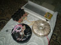
Hi John
greetings well some ugly hand wound ones torridals have worked good
1 ac input voltage 220 volts
2 freqency 50 hz
the black one is 50 0 50 into 2
white one 40 0 40 into 2 i use it for H900 AMP working for a year no problem
and does not heat confirming ITS 2 TURNS PER VOLT
warm regards
andrew lebon
Attachments
Now we can see there is so big difference...
my formula say 172/220 = 0.78 turn per volt
but your data is 2 turns per volt
Where do this data come from? Is this core was a working trafo but somehow it melt down?
This really make me confuse, anybody help?
i would tend to agree with andrewlebon's data as it came from an actual traffo...yours came from the formula....
what you could have done is count the actual tuns from the old windings......
you have different kinds of materials in your cores that is why the difference...
and this is what i am trying to hammer on.....when you are unsure about your core, operate it at lower tesla, < 1T.
Hi andrewlebon,Hi John
greetings well some ugly hand wound ones torridals have worked good
the important is that your trafo worked good,
my toroid even not finish yet
not isolated yet
Hi Tony,i would tend to agree with andrewlebon's data as it came from an actual traffo...yours came from the formula....
what you could have done is count the actual tuns from the old windings......
you have different kinds of materials in your cores that is why the difference...
and this is what i am trying to hammer on.....when you are unsure about your core, operate it at lower tesla, < 1T.
I'm also agree if it was from old original winding
I usually write note of turn each winding & wire diameter if rewind any trafo to compare with the formula
but
it is always safe to do < 1T?
must be safe
but
I'm afraid if the primary resistance to much that can make our trafo maybe not work in its full power since its can't draw more current at primary, must be any minimum value for T?
It is not mentioned yet
Regards
Last edited:
it is always safe to do < 1T?
in my experience, yes......you get lower operating temperatures at the expense of regulation.....
the key is to stay below the knee of the magnetization curve and prevent core saturation, that is the goal of every traffo build....
I'm not sure yet, please help
Already collect enough core & enameled wire but
I have a little problem with the insulation material,
I mean the insulator between layer
please someone give me reference...
I also thinking maybe usual A4 paper 70gsm can be used
my idea is paint it with special varnish so the usual paper can be used
I don't know what the name of "right" paper that usually used for making trafo
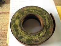
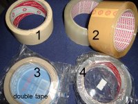
Here what I have, which one could be the best choice?
This some pictures of "isolasi" that what its name here
If this easy available thing painted with special varnish I guess it can be used
Any suggestion will be welcome...
because it will be 300VA or more, so if possible I don't want to any false
Thanks
Already collect enough core & enameled wire but
I have a little problem with the insulation material,
I mean the insulator between layer
please someone give me reference...
I also thinking maybe usual A4 paper 70gsm can be used
my idea is paint it with special varnish so the usual paper can be used
I don't know what the name of "right" paper that usually used for making trafo
Here what I have, which one could be the best choice?
This some pictures of "isolasi" that what its name here
If this easy available thing painted with special varnish I guess it can be used
Any suggestion will be welcome...
because it will be 300VA or more, so if possible I don't want to any false
Thanks
Attachments
- Status
- This old topic is closed. If you want to reopen this topic, contact a moderator using the "Report Post" button.
- Home
- Amplifiers
- Power Supplies
- Iron Core Transformer Formula