Bobsone, thank you for the resources. There are a lot of schematics here as well (found via one of your links):
Circuits Page 9
All require a low voltage DC supply.
Following the KISS principle I ordered a latching push button switch on Amazon. Apparently they have the best prices, beating Digikey and Mouser sometimes by 50%:
Amazon.com: Pushbutton Switches - Switches & Relays: Automotive
Circuits Page 9
All require a low voltage DC supply.
Following the KISS principle I ordered a latching push button switch on Amazon. Apparently they have the best prices, beating Digikey and Mouser sometimes by 50%:
Amazon.com: Pushbutton Switches - Switches & Relays: Automotive
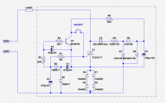
This circuit emulates a mechanical SPST switch controlled by a push-button.
As its mechanical model, it is 2-wire and requires no auxiliary supply.
It will waste ~1.5V ac in the ON state and leak ~1mA in the OFF state.
Since the triac is DC controlled, it is compatible with any type of load.
On a cold start, it will start in the OFF state.
The version shown is low-power (<200VA), but it can easily be upgraded; in fact, making it larger will ease the trade-offs (the load current needs to be at least 3x the Igt).
The 1N4002's and the triac need to be beefed up, but other than that, little modifications are required.
The circuit is designed for a sensitive gate triac (Igt<10mA), because it is intended for low power, but it could accommodate a standard triac if the power controlled is >100VA: the 68Ω needs to be lowered to accommodate the triac's requirement, and the 470µF's need to be increased in the same proportion
Edit: the circuit is shown with a 230V supply, but it will work with 120V as well; C3 might need to be increased if you want to switch ON and OFF repeatedly very quickly, but I don't think it is advisable anyway
Attachments
Last edited:
Hi,
Thinking to make a simplified version (without the led and its resistor) of the circuit proposed by Bobsone with a 2 poles relay to switch ON/OFF a poweramp.
So, related to the circuit from Bobsone's first link (Toggle ON / OFF Switch - Electronics-Lab) and the schematics in the Circuits Page 9 (Circuits Page 9), I'm not sure to correctly understand "One disadvantage is the relay may be engaged when power is first applied. To solve this problem, you could tie the reset line (pin 4) to another resistor/capacitor combination with the capacitor at ground and the resistor at the +V point. This will cause pin 4 to be held near ground for a short period which will reset the output when power is applied.".
Does it mean that pins 8 and 4 of the 555 have to be disconnected (leaving pin 8 connected to the +V) and that the pin 4 alone has to be connected to the +V through a resistor and to the ground through a capacitor? Which values then for these R and C?
Thanks in advance for replies/comments!
Edit: will something like attached work (given I use main AC rated relay and supply 120VAC instead of 12DC as pictured)?
Yes. This is THE way to do it when relays are more fashionable than sand-state. Millions of factory machines use just that plan.
You have noted that it needs two buttons (or an on/off/on 3-position switch)?
Do you mean an old fashion 'télérupteur' (or latching switch according to wikipedia)?
Well... it's rather bulky and noisy, and the push button is not really aesthetic on the front panel")
Anyway, I will try to set a circuit to command a 2 poles relay. Still have to get one to check the connections.
Well... it's rather bulky and noisy, and the push button is not really aesthetic on the front panel
Anyway, I will try to set a circuit to command a 2 poles relay. Still have to get one to check the connections.
Yes, the name is 'telerupteur' in French, the push button can be any switch as long as it can feed 220V ac to the relay coil of the telerupteur.Do you mean an old fashion 'télérupteur' (or latching switch according to wikipedia)?
Well... it's rather bulky and noisy, and the push button is not really aesthetic on the front panel
Indeed, it is noisy....well, you do know when it switches.
Last edited:
...'telerupteur' in French, the push button can be any switch as long as it can feed 220V ac to the relay coil of the telerupteur.
Indeed, it is noisy....well, you do know when it switches.
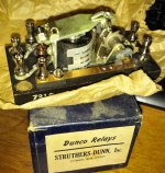
Agh!! These are ALL over Amazon France, but almost impossible to find on the US market. (Why I paid a lot for the S-D antique.)
SAME mechanism: coil ratchet cam switch.
Different coil voltages available. 230V is simple. 24V may allow less-safe wire on the buttons but needs a LV power source.
For EUR14 you get light plastic parts. EUR30+ gets a DIN-mount. Link.
Spec Sheet
ONE found randomly at a place that will ship to me. (This one is 24V DC.) Link. More.
Last edited:

A latching relay would work a charm. Too bad they're so expensive.
Really? How about: https://uk.farnell.com/omron/g5rlu1aedc5/relay-spst-no-250vac-24vdc-16a/dp/2432859?st=latching relay
You are responding to a VERY stale post: late 2011.
- Status
- This old topic is closed. If you want to reopen this topic, contact a moderator using the "Report Post" button.
- Home
- Amplifiers
- Power Supplies
- On/Off switch using momentary push button