I am in the midst of designing something of a 'universal power supply' for audio power amplifiers in a seperate enclosure.
Most electronics these days seem to incorporate a 'push on, push off' momentary switch design rather than a latching switch.
Any references of how to design this?
The switch I am considering using (latching) is a 3 amp/250V coupled to a 300 VA 25-0-25 torroidal. However, would prefer the 'push on, push off' scenario. I guess there should be no problem with the latching switch handling the 1.25 Amps @ 240V nominal current but am a little concerned about surge currents at switch on so using a relay might be the better option - I mention this as possibly a relay would be an integral part of the first question requirements.
Your thoughts would be appreciated.
You can get mechanical switches which incorporate a 'push to change state' operation, but whether these are available in panel mounting form I don't know. Single-pole versions are sometimes used for lighting, but you really need double-pole for safety. You basically need a flip-flop. The advantage of doing this mechanically is that Off really does mean Off; an electrical flip-flop needs a power supply.
Personally I prefer the certainty of a proper toggle-type switch, whatever external shape it has.
Personally I prefer the certainty of a proper toggle-type switch, whatever external shape it has.
Use relays to achieve the latch ON latch OFF action.
There are circuits on the Forum.
I seem to recall they use three ordinary (cheap) relays to achieve latching with a momentary contact switch.
All the switching and relays can use low voltage DC with just the final Mains relay at high voltage.
Is this the mechanical equivalent of a bi-stable?
There are circuits on the Forum.
I seem to recall they use three ordinary (cheap) relays to achieve latching with a momentary contact switch.
All the switching and relays can use low voltage DC with just the final Mains relay at high voltage.
Is this the mechanical equivalent of a bi-stable?
Last edited:

Perhaps you're looking for something like this (using D Flip-Flop)
Single-Pushbutton ON/OFF Power Control - Maxim
other debouncing circuits using logic gates.
Switch Debouncing - The Lab Book Pages
You also need an High side mosfet driver with built in charge pump to retain the boostrap voltage. Something like this:
LM9061 - Power MOSFET Driver with Lossless Protection
You'll need a small aux DC power supply to power the logic gates and high side driver.
A small saturable inductor could be used in serious with the high side switch mosfet to limit initial current rush. Alternative you could couple the power switch with AC zero crossing so that the mosfet only turns on just after the zero crossing for a slow start. Or you can use a high value gate resistor (perhaps 100 to 1K ohms) but use a parallel diode to speed up gate turn off.
I have mistakenly purchased a push button (link below) instead of a switch for my preamp project:
ULV4F2B11544 E-Switch | Switches | DigiKey
Is there an easy way to make a switch out of it?
I don't want to change the button (I like it and I already made a proper cutout in the front panel) or add auxiliary power supply to drive a denouncing circuit (this would be an overkill for the small project I have). Something simple that can run off of the mains AC would be great.
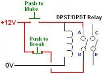
Edit: will something like attached work (given I use main AC rated relay and supply 120VAC instead of 12DC as pictured)?
ULV4F2B11544 E-Switch | Switches | DigiKey
Is there an easy way to make a switch out of it?
I don't want to change the button (I like it and I already made a proper cutout in the front panel) or add auxiliary power supply to drive a denouncing circuit (this would be an overkill for the small project I have). Something simple that can run off of the mains AC would be great.
Edit: will something like attached work (given I use main AC rated relay and supply 120VAC instead of 12DC as pictured)?
Attachments
Last edited:
Now that I look at my sketch I see that it requires double pole single throw. My button is single pole single throw, so it will not work. Does anyone know of an alternative schematic? I am hearing something about using 3 relays but I cannot find anything.
I don't mind getting a different push button switch (that will offer on/off latching action) but so far I cannot find one that fits my cutout (19.2mm diameter) and is black color (my front panel is black). This one looks nice but it is silver:
Electronic Components and Parts Search | DigiKey Electronics
jcarr, can the circuits you linked be adopted to work off of mains directly? I want to try to avoid adding another transformer in the chassis.
Now that I look at my sketch I see that it requires double pole single throw. My button is single pole single throw, so it will not work. Does anyone know of an alternative schematic? I am hearing something about using 3 relays but I cannot find anything.
I don't mind getting a different push button switch (that will offer on/off latching action) but so far I cannot find one that fits my cutout (19.2mm diameter) and is black color (my front panel is black). This one looks nice but it is silver:
Electronic Components and Parts Search | DigiKey Electronics
jcarr, can the circuits you linked be adopted to work off of mains directly? I want to try to avoid adding another transformer in the chassis.
You can create a latching relay with the addition of a single DPDT relay with a main AC rated coil (e.g. 115VAC coil) and another momentary button.
WIRING:
You wire one momentary pushbutton (for "ON" operation) in series with the relay coil. When you push the button the relay will operate (let's call this "ON"). But when you release the button the relay will return to its original "OFF" position. To prevent the return to OFF what you do is wire both DPDT contacts to the AC mains (before either of the momentary buttons). One of these contact pairs is then wired in parallel with the momentary button that you used to turn on the relay. Once the relay contacts close (e.g. when you push the ON button), even if you release the ON momentary button there is still AC power applied to the coil and it will stay on. Forever! So you also need a way to turn it OFF again. This is where the second momentary button (let's call it the "OFF" button) comes in. This is inserted into the AC mains before any of the other connections. When you push the OFF button all AC power is removed, the relay returns to its OFF position, and you are back where you started.
If you can live with two buttons, one for ON and one for OFF, or even a momentary ON-OFF-ON(2) type button, you can create this type of control. Instead of the button (or switch) taking the stress of making and breaking the current, it is the relay that is doing that job and the button has very little current to switch. This means you can use just about any button that is rated for mains AC voltage.
Anyway, it's kind of putting lipstick on a pig, but it'll work.
P.S. This is for switching one pole of the mains that leads to your amplifiers. If you need to switch live and neutral, you will need to use a 3PDT relay.
You can create a latching relay with the addition of a single DPDT relay with a main AC rated coil (e.g. 115VAC coil) and another momentary button.
Thank you. I have a cutout only for one button so two buttons is not an option.
It appears my only practical option is to try to find a latching Off-On push button diameter that fits my front panel cutout. Adding an extra circuit with DC power supply is an overkill.
Hi
If you are thinking about a flipflop option, there are a lot of these switch circuits and boards available online.
I have made the following circuit to switch an ATX power supply and it works well. Because it was powered by 5V DC from the ATX supply I didn’t need to include a small step down transformer and because it is switching the ATX 5V trigger I didn’t include the relay.
Toggle on / off switch
Toggle ON / OFF Switch - Electronics-Lab
However, in your case I am guessing you will need to include a mains stepdown circuit in the flipflop design so I have added two options that I have explored. I have a HLK-PM01 AC-DC on a delayed flipflop that I made, it works well and from the tests I have seen online people are happy with its construction and operation.
HLK-PM01 AC - dc 220v bis 5V Step-Down Netzteil Modul
1 Stuck HLK-PM01 AC - dc 220v bis 5V Step-Down Netzteil Modul | eBay
Details zu Print Trafo 230V / 12V 2,1VA 175mA BV EI 304 2082
Print Trafo 230V / 12V 2,1VA 175mA BV EI 304 2082 1Stuck | eBay
As has been mentioned, debouncing the mechanical switch “may” be necessary, if you are like me (a novice) and don’t have any way to measure/see what’s happening in the circuit then although switch bounce generally isn’t overly difficult to resolve (and if it is actually an issue) it may require a little research and testing.
As for the load side relay selection and any needed inrush control, hopefully others in the forum can help solve any issues.
Just for reference, here are some other examples (including an ebay special) I have seen;
Softstart Module
Hypex Electronics webshop
SST01 Softstart for toroidal transformers
SST01 Softstart for toroidal transformers - Sjostrom Audio
Soft Starter Start-up For Power Amplifier,W/ Thermal Dectector,Protect
https://www.ebay.com/itm/Assembled-...318622?hash=item1c2145fade:g:XoAAAOxyKsZRxVtY
Regards.
- Status
- This old topic is closed. If you want to reopen this topic, contact a moderator using the "Report Post" button.
- Home
- Amplifiers
- Power Supplies
- On/Off switch using momentary push button