Hello All,
A couple of days ago I asked a question about an Audio Buffer for a 125ASX2, all the replies were very helpful and I have decided to try and build one of the recommended Buffers. I am having trouble figuring out the Power Supply for the OP-AMP, the 125ASX2 has an unregulated aux supply that outputs ±24VDC and the Audio Buffers need ±15VDC.
I've spent the last day looking through the forums and found many designs all with vary levels of complexity. Unfortunately space is an issue in this case so a smaller circuit would be better.
It seems that the Super-Reg is considered one of the best however, it is a rather complicated circuit with many components and takes up quite a bit of space.
On the other hand, the LM317/LM337 has five components, takes up very little space but is rather noisy by itself.
There are circuits like Fred Dieckmann's "one transistor addition to the three terminal regulator" and this "Clean-up Shunt" that could be space efficient but maybe not suitable...
The Question
What would you recommend as a good, simple (LM317/LM337 based?) Low Noise Voltage Regulator for a simple OP-AMP Buffer?
Any help would be greatly appreciated.
Thank you in advance,
Alex
The standard LM317/337 circuit as is is already excellent for low noise. Trying to clean the output even more might just be overkill when opamps are fed.
Opamps themselves have a very good power supply rejection ratio (PSRR). That PSR suppresses the very little noise that might still be there after the regs even quite a bit more.
In fact, when space is really an issue, I would simply use 7815/7915 combo with HF bypassing caps as close to the regs as possible. Dissipation permitting, you might even use the smaller 100 mA version (78L15 and 79L15).
Thanks Jitter, that makes things a lot easier!
Would it be a good idea to match the voltages of the LM317 and LM337 using matched resistors or a potentiometer? Would the Opamps care if the positive rail was (extreme example) say 15.24v and the negative rail was 14.91v?
Thanks again.
Kind regards,
Alex
Would it be a good idea to match the voltages of the LM317 and LM337 using matched resistors or a potentiometer? Would the Opamps care if the positive rail was (extreme example) say 15.24v and the negative rail was 14.91v?
Thanks again.
Kind regards,
Alex
Thanks Jitter, that makes things a lot easier!
Would it be a good idea to match the voltages of the LM317 and LM337 using matched resistors or a potentiometer? Would the Opamps care if the positive rail was (extreme example) say 15.24v and the negative rail was 14.91v?
Thanks again.
Kind regards,
Alex
No, that's not necessary. PSRR also reduces the effect of out of balance power supply. An opamp still works fine on (e.g.) a +/- 15 V power supply with +/- 0.5 V tolerance on both rails.
Besides, even if power supplies were perfectly symmetrical, the + and - input are never 100% identical leading to DC offset on the output anyway.
In critical DC-coupled applications output offset needs to be nulled and that allows only for the use of opamps with offset adjustment capability. In audio DC is usually dealt with by DC-blocking caps to circumvent the whole offset adjustment procedure (you just don't want that time consuming hassle in mass production). The popular dual opamps in 8 pin cases don't have offset adjustment available.
An aside, but don't use the DC offset adjustment if you don't absolutely need it on any opamp. It is an easy and excellent way to utterly ruin PSRR. ( - and if you do need it, ensure the supplies are filtered before the bias adjust pot biasing supply is heavily pre-filtered)
Similarly teh adjustment should only be used to null the opamps output to 0v - not 'system output' (eg at the output jacks). That often ruins performance by excessively unbalancing the LTP pairs internally!
Similarly teh adjustment should only be used to null the opamps output to 0v - not 'system output' (eg at the output jacks). That often ruins performance by excessively unbalancing the LTP pairs internally!
Last edited:
My advice would be to use the 317/337 with 10uF bypass. If you put a cap on the output as well, use something like a tantalum which will have 4 to 8 ohms of ESR and will damp any resonances. Don't go above 10uF as you will bring the resonance of the o/p impedance into the audio band.
IIRC you shouldn't need a buffer. The input Z is 8k I think and anything should be able to drive that. If you put an op amp in, then take the opportunity to put in a little filtering. 80 - 1000kHz, single capacitor around 220pF.
CT
IIRC you shouldn't need a buffer. The input Z is 8k I think and anything should be able to drive that. If you put an op amp in, then take the opportunity to put in a little filtering. 80 - 1000kHz, single capacitor around 220pF.
CT
Regulators
For Your Information:
Simple Voltage Regulators Part 2: Output Impedance
Using 3-pin regulators off-piste: part 1
For Your Information:
Simple Voltage Regulators Part 2: Output Impedance
Using 3-pin regulators off-piste: part 1
Noise or output impedance do not control sound quality...
sorry but that is just to much of a generalisation to be left alone. it depends very much on what you are driving with said circuit. for headphones of low impedance for example the output impedance has a rather audible effect on sound quality
Noise or output impedance do not control sound quality...
Then you may have never heard a preamp or amp whose output is modulated by power supply problems.
You can test for this pretty easily. Build a simple JFET preamplifier with a gain of 10X. Inject A-weighted noise into Vcc or Vee and measure the point at which it becomes "hearable" on a quiet recording. For a moving coil phono preamp this is going to be a pretty low number!
Output impedance is tricky to measure below 10 milliOhms or so. Walt Jung, in a lab setup was able to measure it below 10 microOhms. If you want to demonstrate for yourself the impact of supply output impedance, take a look at the power supply Vcc or Vee when a highly percussive instrument is played. Or, one could look at the effect (IM) when a clock signal is coupled to a preamplifier or buffer supply line.
It's all in the listening. I use SY's "His Master's Noise" MC phono pre which is not in the same noise category as some of the JFET designs, but it sounds sweet nonetheless. (Should mention that the current source for his design is very low impedance depletion MOSFET.)
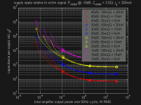
Yes, in the end it's the listening which matters. But it's not particularly difficult to design for supply impedance in conjunction with control loop PSRR. The attached figure's a fairly typical example but there's a lot of information packed into it, so let me explain what it's showing. The four sets of curves indicate the magnitude of a linear supply's ripple voltage relative to an amp's output power as a function of available bypass capacitance. For example, if you have a fairly decent 10,000uF reservoir cap arrangement with power planes and your amp's playing at a total output power of 10mW RMS then the design will land right around the bottom pink curve---the supply impedance will be roughly 25mOhm + 5nH and the ripple voltage will be 10dB larger than the signal that's going out to the driver. So if you want to minimize supply artifiacts on the output---say 80dB below the signal---then the amp's control loop needs to have 90dB PSRR.
There are many different cases here as every supply's impedance varies with layout and capacitor selection, different amplifiers have different quiescent current (Iq) draws, and different drivers present different impedances and efficiencies. The basic analysis doesn't change much from design to design, though; most drivers are about 90dB efficient and most listening happens at conversational levels around 55dB. So most home audio power amplifiers spend most of their time operating in the range of 100uW to 10mW. This is the range in which the bias current in the output devices dominates the amplifier's power consumption and hence the amount of ripple in the supply---I've chosen Iq = 200mA and 3 ohm load here as that's representative of a class AB stereo amplifier driving the lower impedance range of most speakers. 100uW to 10mW is also unfortunately the range where the supply impdance has a large impact on the size of the ripple relative to the signal going out to the drivers. Since the control loop in most amplifiers only has 70 or 80dB PSRR this is why people hear differences between supply caps and various layout techniques. It's also why most THD measurements on power amplifiers don't show supply issues; typically they're conducted at atypically high output powers of 10W or more where the quality of the supply isn't particularly important.
The next part of this is interaction between channels within an amplifier via the power supply. In a typical two channel amplifier both channels share a single set of reservoir caps. So the supply ripple is a function of the combined output power of both channels. If both channels happen to be playing at the same level this isn't so bad, but usually there's a few dB difference at any given moment between the left and right stereo channel. This is what the Pvictim bit in the figure is about---whichever channel's playing quietly ends up being "victimized" by the louder channel's power consumption creating ripple in the supply. I've chosen 10dB here as a representative number but there are cases, such as biamping with an active crossover, where one's likely to want to be significantly more conservative.
So, from a power supply design standpoint, what all this means is---as a rule of thumb---one needs a way of keeping ripple voltages on the order of 40dB larger than the music off of a power amplifier's output. What exactly off the output means is a matter of personal preference but personally I like to design for 100dB down to keep the IMD floor nice and low. That means one wants PSRR on the order of 140dB, which in turn means it's desirable to operate the control loop from a regulated supply. The LM3x7 parts are attractive here due to their relatively good ripple rejection, the ability to stabilize their reference voltages with the 10uF cap discussed in the last few posts, and their low cost.
If there's demand for it I can write up a preamp version of this analysis, but I think you get the idea. One also needs to check on the regulator's load transient behavior but, usually, the control loop operates in class A and it doesn't matter much.
Attachments
TDA 2040 is rated max supply at 20v.If I use 7818,7918 or 7815,7915 from 30v power supply ,can it drive TDA 2040 to the optimum level ?.78xx,79xx are rated for 1.5A.Or should I parallel each regulator for higher current output.I dont know how much current TDA 2040 actually needs.Im right now running too TDA 2040 from 7815,7915 regulator .
Last edited:
The TDA2040 is internally limited to 4 amps. Rather than parallel 78xx series chips, I'd look into adding a pass transistor or some of the newer vreg offerings with higher power output.TDA 2040 is rated max supply at 20v.If I use 7818,7918 or 7815,7915 from 30v power supply ,can it drive TDA 2040 to the optimum level ?.78xx,79xx are rated for 1.5A.Or should I parallel each regulator for higher current output.I dont know how much current TDA 2040 actually needs.Im right now running too TDA 2040 from 7815,7915 regulator .
Opamps themselves have a very good power supply rejection ratio (PSRR). That PSR suppresses the very little noise that might still be there after the regs even quite a bit more.
I agree - but the story doesn't end there. So I'd like to add a little bit here -
Yes, opamp psrr is very good. You may see this spec'd at 70db or more. *but* - there are caveats:
1) PSRR is not always the same on both rails. Many opamps have better performance on the positive rail, some on the negative rail. Check the data sheets and you will see. Those that spec psrr+ and psrr- are the best, those that spec only psrr+ scare me.
")
2) PSRR is frequency dependent. Some, not all, manufacturers provide curves of PSRR vs frequency. It falls off very quickly. For audio, maybe not an issue - but check the specs.
3) Some opamps have a very nice (joke) unfiltered path from the -rail to the output. Something to be aware of.
- Status
- This old topic is closed. If you want to reopen this topic, contact a moderator using the "Report Post" button.
- Home
- Amplifiers
- Power Supplies
- Simple Low Noise Voltage Regulator?