Hi all,
I've just built a TDA7293 based amp that's being powered by a 28v-0-28v transformer which is in a separate enclosure.
I'm adding a unbalanced to balanced converter board which requires +/-15VAC... I have a little 30VCT transformer that I can use but then I'd have to move to a larger enclosure to fit the two transformers, plus build a new umbilical cord with more strands.
Can I just use voltage regulators (LM7815 or something similar) and tap off of the existing +/- 28v power that I have in the chassis? Is this doable and would this be the better solution?
(Lot's to learn and just trying to figure it out piece by piece)
Thanks for your help!
More info needed on a couple of things...
A 28VAC - CT - 28VAC tranformer will produce +/-38VDC or so after it goes through the rectifiers and filter cap. Are you planning to connect to the AC out of the transformer or the DC after rectifiers somewhere? Or is it that you have +/-28VDC rails?
And a related question... is it really +/-15VAC you need (rectifiers and filter cap on board to make DC) or +/-15VDC?
Assuming here that it is +/-15VDC that you need the LM7815/LM7915 would almost work but there are a couple of hiccups. First they only take 35VDC in, so if you are hooking to the 38VDC you would have to loose a few volts somehow before the regulators. If instead you have +/-28VDC you are OK as is. The other issue is current and heat. How much current does your board need? At 100mA you would need to add a heatsink capable of dissipating (33VDC - 15VDC) * 0.1A = 1.8W or so. With a 28VDC feed that is a bit better at 1.3W.
Last edited:
More info needed on a couple of things...
A 28VAC - CT - 28VAC tranformer will produce +/-38VDC or so after it goes through the rectifiers and filter cap. Are you planning to connect to the AC out of the transformer or the DC after rectifiers somewhere? Or is it that you have +/-28VDC rails?
And a related question... is it really +/-15VAC you need (rectifiers and filter cap on board to make DC) or +/-15VDC?
Assuming here that it is +/-15VDC that you need the LM7815/LM7915 would almost work but there are a couple of hiccups. First they only take 35VDC in, so if you are hooking to the 38VDC you would have to loose a few volts somehow before the regulators. If instead you have +/-28VDC you are OK as is. The other issue is current and heat. How much current does your board need? At 100mA you would need to add a heatsink capable of dissipating (33VDC - 15VDC) * 0.1A = 1.8W or so. With a 28VDC feed that is a bit better at 1.3W.
Hi AGDR.
I want to tap into the 28v-0-28v AC secondary directly (Before the rectifier)
The board requires between (+/-12v & +/-18v AC) as it has it's own diodes & regulator on-board
I'm not sure how much current this preamp draws... Here's a link for your reference
Unbalanced to balanced stereo preamplifier for BTL
Thanks for your reply
What you could do... The Elna's are only rated for 35VDC. You need to replace them (and the other electrolytics) with ones rated 50V or more. The TO220 regs are rated for ~15 watts, so even drawing 250mA with 25 volts dropped by the regs the circuit isn't close to that. If you do choose to fit a heatsink between the two LM317s, you'll need insulators between each regulator and the heatsink because the tabs are at different potential.
Actually the smaller electrolytics are probably fine if on the output side of the regs.
Cool... I was thinking that the smaller caps were seeing the post-regulated voltage... Do you think I could get away with lower value caps, like 2,200uF @ 50v? (In the event that 3,300uF's are physically too large)
Just do a visual or ohmmeter trace of the reg outputs for the cap connections. You don't really want one blowing its top. 2200uF should be fine, but it might be a good idea to test it out. Leave some lead length in case you want to try paralleling another reservoir cap. Resolder and trim the leads if one will do.
I want to tap into the 28v-0-28v AC secondary directly (Before the rectifier)
The board requires between (+/-12v & +/-18v AC) as it has it's own diodes & regulator on-board
Thanks. The 7815/7915 regulators only work with DC and not AC so I needed to clarify that.
")
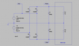
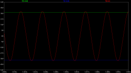
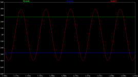
If you feed the +/-28VAC into the +/-15VAC terminal block on your board, here is what happens - pictures and plots below. The LM317/337 regulators on your board are good for an absolute maximum of 40VDC input, a bit more than the 7815/7915. The first plot shows that you get about 38V out of the rectifiers on your board into the regulators. If you change the caps to 50V, like sofaspud says, seems like it would be OK.
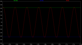
However you want to stay a few volts below that 40VDC max as good practice and the incoming AC line voltage can vary +/-10%. If it varies in the "up" direction during a lightly loaded condition the second plot shows what happens. Now you are up to 43VDC and the regulator chips are not happy.
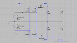
If it were me I would add 10V 5W zener diodes after the rectifiers, like this one
Digi-Key - 1N5347BGOS-ND (Manufacturer - 1N5347BG)
to knock the incoming DC voltage down by 10VDC. The second circuit and plot below shows what you get. The output voltage is now 28VDC nominal, as shown, or 33V max with a 10% line voltage fluctuation. With the change you would be OK with the existing 35V electrolytic capacitors. At 200mA that would only be 10VDC * 0.2A = 2W in the 5W zeners so they are happy too (I wouldn't recommend using a 2W zener, stay with 5W). Note that 10V zener part number on the simulation isn't the right wattage - just what I had in the database - sims don't care about smoke.
To add the zeners you would have to do a bit of "skywiring". Study my circuit diagram below and de-solder and pull out the two ends of the diodes that have the cathodes connected together. solder them together in the air along with the cathode of a zener. Then run the anode of that zener back into one of the holes where the diode leads went and solder. Then repeat for the other two diodes that have the anodes connected together. Pull out the anodes, solder them to together with the anode of a second 10V zener, then stuff the cathode of that zener into one of those two holes and solder.
The 317/337 regulators are good for 50 degrees C per watt with no heatsink, from the datasheet. With a max of 33V (with the two 10V zeners added) in and 200mA current draw max (a guess) that gives (33V - 15V) * 0.2A = 3.6W. That would be 3.6W * 50C/W = 540C, but most junctions max out around 150C. So you definitely need a heatsink. But like sofaspud said you may be able to slip one inbetween the two regulators if you use insulators.
Attachments
Last edited:
The LM317/337 regulators on your board are good for an absolute maximum of 40VDC input
This is incorrect.
LM317/337 are good for Vin-Vout<40VDC. In other words, the maximum input voltage is 40VDC greater than the output voltage. You can actually use them in high voltage supplies because of this (100+V, for example). They will have absolutely no trouble here, and are far lower in noise than LM78xx/79xx regulators.
True, they are floating regulators, but the problem comes at the instant of startup when the output caps are discharged, and also in the event of an output short. Then you are back to more than 40V across the regulators. Some extra work has to be done to protect against that. Good writeup here:
http://www.national.com/an/LB/LB-47.pdf
Edit: I should add - I would use the zeners, but that is just me. BrianDonegan is 100% correct that the regulators could be used as is, no zeners, and should work just fine. I've seen a lot of circuits >40V built up that way with the regulators floating and no added protection circuitry. So take your pick.
Last edited:
Brian,
you are right.
BUT!!!!
you are choosing not to forewarn the Members that at start up, when the 317 has zero volts between output and ground/adjust the regulator sees a momentary over-voltage. This is when it could be damaged to fail later, or damaged to not perform to specification, or instantly blow up during the start up procedure.
Yes, I didn't get into the detail of the LM317 implementation at all. Still very doable, and plenty of examples out there for that part.
Here is an app note about using the LM317 for a high-voltage supply:
http://www.national.com/ms/LB/LB-47.pdf
Here is an app note about using the LM317 for a high-voltage supply:
http://www.national.com/ms/LB/LB-47.pdf
Last edited:
- Status
- This old topic is closed. If you want to reopen this topic, contact a moderator using the "Report Post" button.
- Home
- Amplifiers
- Power Supplies
- +/- 15v AC required for balancing converter board