Hi to all I have a transformer with dual secondaries and dual primaries. First question is Can I use the dual secondaries as center tap with one bridge without having any 50 Hz hum? Do I have to be carefull in the phases?
Also Is there a posibility to have a hum if I connect the primaries in series (240Volt) but in not correct phase? What if I have two of those trafos? Do I have to pay attention in the phase between the two trafos? The problem or the key here is the 50Hz hum. I have the situation described above and I experiance some audible hum.
I would apreciate any comments
Thanks
You can use two separate secondaries as one CT secondary. Just connect the end of one winding to the start of the other. The join is the centre tap. The phasing will probably be indicated by leadout colours, but you can check with an AC voltmeter. You can use one bridge with a CT sec to get + and - DC.
If you connect primaries in the wrong phase you will hopefully blow a fuse or trip a breaker. Failing that the transformer primary windings will get very hot and emit smoke.
Put up a diagram if you want further comments on what you have done.
If you connect primaries in the wrong phase you will hopefully blow a fuse or trip a breaker. Failing that the transformer primary windings will get very hot and emit smoke.
Put up a diagram if you want further comments on what you have done.
If you use a Dual secondary with a single bridge rectifier, you MUST convert the Dual secondary to Centre Tapped. Do as DF suggest.
To avoid potentially damaging mishaps with incorrect wiring, always power up mains powered projects via a bulb tester.
It is that good that even with the Dual Primaries mis-wired as an effective short circuit that the mains fuse does not blow.
To avoid potentially damaging mishaps with incorrect wiring, always power up mains powered projects via a bulb tester.
It is that good that even with the Dual Primaries mis-wired as an effective short circuit that the mains fuse does not blow.
The Dual Primaries are usually 115Vac.
Connect them in parallel for 110/120Vac operation.
Connect them in series for 220/240Vac operation.
Connecting one primary with the incorrect phase will turn the transfomer into an effective short circuit across the mains.
The transformer Primaries will try to absorb many kW of power until something blows.
Use a bulb tester.
To avoid potentially damaging mishaps with incorrect wiring, always power up mains powered projects via a bulb tester.
A little mechanical noise may be unavoidable. Try mounting using rubber grommets, but be sure to maintain a ground connection for the frame.
Hum on the output, unless severe, is unlikely to be a transformer issue but due to poor grounding or inadequate smoothing. Many people route the reservoir charging currents through their star ground, then wonder why they get hum.
Hum on the output, unless severe, is unlikely to be a transformer issue but due to poor grounding or inadequate smoothing. Many people route the reservoir charging currents through their star ground, then wonder why they get hum.
What do you mean by "Many people route the reservoir charging currents through their star ground" exactly? It is not clear to me.A little mechanical noise may be unavoidable. Try mounting using rubber grommets, but be sure to maintain a ground connection for the frame.
Hum on the output, unless severe, is unlikely to be a transformer issue but due to poor grounding or inadequate smoothing. Many people route the reservoir charging currents through their star ground, then wonder why they get hum.
The link between the negative side of a bridge (or the secondary centre-tap) and the reservoir cap -ve terminal carries charging pulses. It should simply connect these two points together. There should be a separate link from the reservoir -ve to the smoother -ve, and then from there to the star point.
What many people do is connect the bridge (or CT), reservoir -ve and smoother -ve with three separate wires to the star. As a result the charging pulses go through the star. This would be OK if the star had zero resistance, but it doesn't. Even a few mm of thick connector is enough to generate a hum voltage if it has charging pulses through it.
What many people do is connect the bridge (or CT), reservoir -ve and smoother -ve with three separate wires to the star. As a result the charging pulses go through the star. This would be OK if the star had zero resistance, but it doesn't. Even a few mm of thick connector is enough to generate a hum voltage if it has charging pulses through it.
Many Members recommend this fault in grounding.Many people route the reservoir charging currents through their star ground, then wonder why they get hum.
It is asking for Hum & Buzz problems.
Go to "latest Articles" Read
Audio Component Grounding and Interconnection - diyAudio
I am attaching the powersupply as a jpg file.Is anyone has any idea why I get 100 Hz hum
I have seperate trafos for each channel and different secondaries for the low power stages (regulated with lm317 - 337) and the output stage. Ths Power supply is used in a SE CLASS A amp with 2,3 Amp per rail tota 4.5 amp per channel.
thnx.
I have seperate trafos for each channel and different secondaries for the low power stages (regulated with lm317 - 337) and the output stage. Ths Power supply is used in a SE CLASS A amp with 2,3 Amp per rail tota 4.5 amp per channel.
thnx.
Attachments
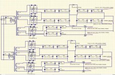
I attach a new photo as it is. Do you think that the 100nf capacitors as they are connected accross the bridges contribute to the hum? I thought so and remove them, but the same situation. I have a week trying to find what is going on. What are your objections to this layout? Do I need more capacitance?
Any help it will be welcome.
Any help it will be welcome.
Attachments
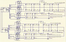
Also if someoune is noticing the low power rectification is done with one bridge and I connect the ground from the connection of the two secondaries to the ground coming from the rectification for the output stage (two bridges). Do you think that this action fills with dirty content the common ground?
- Status
- This old topic is closed. If you want to reopen this topic, contact a moderator using the "Report Post" button.
- Home
- Amplifiers
- Power Supplies
- Dual secondaries with one bridge