Hi,
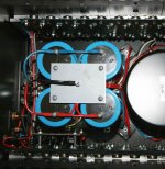
I have two mono-amps and these are using four 27 year old 30,000uF caps each.
They're are preceded by two 35A bridge rectifiers that are mounted with their backs on the metal chassis.
Question is:
I can get 8 new ones with a 5.5 mOhm ESR and 21.4A max Ripple current.
These are much better values than I have know and they're new of course.
Only the capacitance is 100,000 uF per cap.
I already placed a big Megasurge thermistor of 10 Ohms to dampen the inrushcurrent but I'm still a bit worried about the strain on the bridges at normal operation and idling.
Suppose I mount them and the bridges stay relatively cool is there still a problem then?
The old and the new have both 80Volt ratings and I can't get any higher voltage in the same priceleage as this one.
I know about the RIFA PEH169 33,000uF 100Volt cap preference...")
Any advice?
I have two mono-amps and these are using four 27 year old 30,000uF caps each.
They're are preceded by two 35A bridge rectifiers that are mounted with their backs on the metal chassis.
Question is:
I can get 8 new ones with a 5.5 mOhm ESR and 21.4A max Ripple current.
These are much better values than I have know and they're new of course.
Only the capacitance is 100,000 uF per cap.
I already placed a big Megasurge thermistor of 10 Ohms to dampen the inrushcurrent but I'm still a bit worried about the strain on the bridges at normal operation and idling.
Suppose I mount them and the bridges stay relatively cool is there still a problem then?
The old and the new have both 80Volt ratings and I can't get any higher voltage in the same priceleage as this one.
I know about the RIFA PEH169 33,000uF 100Volt cap preference...
Any advice?
Last edited:
The bridge recs will run just as cool even with the greater capacitance. When idling and running the energy dissipated in the amp is essentially the same whether 10 or 100,000uF is present. So that determines how hot the bridge gets... and in this case it stays the same average temperature.
The theoretical problems come at initial charging (switch on) and whether the surge capability of the bridge is exceeded. And if you mean you have 400,000uf per bridge then that's quite a lot in anybodies money lol. And thinking about it the larger capacitance means that the voltage across the caps (ripple) is less and yet the same energy has to be put into the system. This means that the conduction angle of the bridge is correspondingly less... in other words it conducts "harder" (more current flow) but for less time each cycle. That again needs looking at to see if the peak ratings of the bridge are exceeeded.
This is one of those questions that's tough to answer as wiring resistance etc plays a huge part in determining absolute max currents at a practical level.
Thanks for the reaction Mooly.
It's 400,000uF for two MDA-3502P rectifiers.
So it's 200,000uF per rectifier.
Surge problem is managed with the 10 Ohm thermistor.
I've had a circuitbreaker in a same type of amp that tripped (the on/off switch of the amp) frequently but after I had installed the thermistor that problem did not reoccur.
If you talk of a peakrating which value should I look at then?
The 'Peak Forward Surge Current'?
I've supplied the datasheet of the MDA-3502 maybe you can look at it.
In general do you think it's a good practice to substitute 27 year old large can capacitors in a Class A amp? Or should I just wait till they fail or start to hum?
What will happen if the peakratings of the bridges are exceeded?
I'm sorry for these questions but I'm not a technician and you guys are the best source I have.
Attachments
Hi Brian,
There are 2 problem areas.
First is the turn-on surge to initially charge the capacitors. You have addressed that with the thermistor.
Second is, as Mooly points out, the capacitor re-charge current that happens every half-cycle. This current while very short in duration is very high, and is proportional to the circuit impedance (ESR, transformer and mains) and the DC load current. The critical spec for this is the rating for I squared t. That is 25,000A for 1 mS, non-repetative. Because the re-charge current is repetative and uncertain (you have no control over the variables) I would derate this significantly, to about a 25A repetative peak current (my "rule of thumb").
Given high quality caps, you should therefore consider a series inductor between the rectifier and capacitor. You only need a few mH of air cored inductor (speaker crossover inductors) to limit the di/dt to a safe level. This has 3 benefits, it speads the current flow over a longer time so it has a lower peak, it kills RFI (ie mains hum invading the rest of your amp) caused by a high rate of change of current and finally, gives you a cleaner DC voltage.
John
Like this:
ALEPH 1.2 POWER SUPPLY
or
http://www.lifelongenjoyments.net/audio/images/aleph2_pswire.jpg
Any suggestions which and where I should buy these air inductors and what values.
Are there any quality issues?
ALEPH 1.2 POWER SUPPLY
or
http://www.lifelongenjoyments.net/audio/images/aleph2_pswire.jpg
Any suggestions which and where I should buy these air inductors and what values.
Are there any quality issues?
Peak Forward Surge Current. Single 60Hz Half-Sine Wave Superimposed on Rated Load (JEDEC Method). TJ = 150O C =400 amps
If its not getting hot, it should be fine, the transformer will limit the current it has its own inductance..
Thats right, except between rectifier and capacitors.
Dosnt matter. The current flows in a loop, so as long the inductance is in the loop ...
Thats right, except between rectifier and capacitors.
Available at DIY or hobby electronic shops, you should have some locally, or Digikey or Mouser etc. Anything around 1mH but a higher current rating is better, that is 16 or 18 gauge wire, to reduce losses and heat.
Will this size do the job?
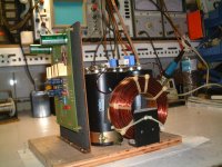
My amp looks like this. (not the DIY super Aleph 1.2 at the left picture of course)
What would be the ideal position to place the Inductors?
I would like not the cut the wires or have the inductors on top of the connecting plate that parallels the caps.
Attachments
The charging pulses are not that fast (and rather rounded so not a lot of high harmonics), the RFI should be filtered prior to the transformer, and snubbing caps should eliminate the rectifier switching noise. Then the inductors dont do much besides reducing your average rail voltages
The charging pulses are not that fast (and rather rounded so not a lot of high harmonics), the RFI should be filtered prior to the transformer, and snubbing caps should eliminate the rectifier switching noise. Then the inductors dont do much besides reducing your average rail voltages
Like this you mean?
Attachments
the RFI should be filtered prior to the transformer
I've got a Siemens 1kVA Isolation transformer?
Any good for filtering?
I've got a Siemens 1kVA Isolation transformer?
Any good for filtering?
No thats not a RFI filter. There are IEC power conectors (the thing you plug your power cord into on the amp) that have built in RFI filters. (so no RFI gets into the chassis thru the power cord).
No thats not a RFI filter. There are IEC power conectors (the thing you plug your power cord into on the amp) that have built in RFI filters. (so no RFI gets into the chassis thru the power cord).
I found those IEC RFI filters (Schaffner makes them) so I know what you mean and I hope that they fit.
Did you see those 5000pF snubber caps around the CSB252 25A, 350A max single surge bridge?
This bridge feeds six 22,000uF caps on a railvoltage of 90V.
Q= 11.8 Coulomb
P = 1/2 C*V2 = 534,6 Joule
The MDA3502 35A bridge with 400A max single surge would be exposed to 11,3 Coulomb and 313,6 Joule.
Do these snubbercaps also lower the di/dt value?
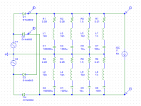
Seems like most of your questions would be best answered with some Spice simulation. Intuitively, snubber caps in parallel with the diodes should relieve peak current only when the energy stored in the snubbers is significant compared to the energy consumed by the load. However, I'd never actually run the analysis and needed to throw together a supply ladder to look at some other stuff anyway. Hope the attached helps. Plot in the middle is the current draw through the diodes for the schematic as shown. Plot at right is the same thing but with 100nF snubbers in parallel to the diodes. No meaningful difference.Any advice?
Attachments
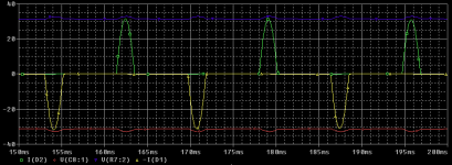
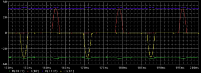
Adding resistors won't increase the snubber caps' energy storage. If, by in series you mean in series with the rectifier diodes rather than in series with the snubbers, yes, you'll create an RC filter with a pole well below 1Hz. That's probably not what you want and 1W probably not enough even if it is. A little filter design work and some verification in Spice should lead to a better choice of cutoff frequency and parts selection.
You may find this article of interest if you have not seen it before. I agree with previous posters that it should have no effect on steady state current draw. Leakage current through the caps may increase slightly, but still will be insignificant.
You may find this article of interest if you have not seen it before. I agree with previous posters that it should have no effect on steady state current draw. Leakage current through the caps may increase slightly, but still will be insignificant.
Thanks a lot Ron.
Very nice link indeed it explains a lot in simple terms for technical lefthanders as I am. It looks this is the guy that made the software tool PSU Designer II.
I knew I could have a problem with the inrushcurrent but after a long and fruitfull l discussion with Mehdi Samii (VP Engineering at Ametherm Inc. manufacturer of inrushcurrent supression thermistors) I decided to use one of their products to smooth out the inrush considerably. The thermistor I have chosen can dissipate 1200 Joules peak and that should adequate.
- Status
- This old topic is closed. If you want to reopen this topic, contact a moderator using the "Report Post" button.
- Home
- Amplifiers
- Power Supplies
- High capacitance vs load on Bridge rectifiers