Hi everybody,
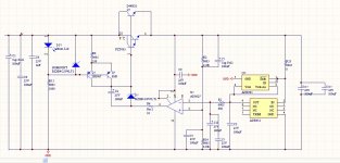
I designed this voltage regulator based on what I found on "Improved Positive/Negative Regulators" by W.Jung.
I know that there are a lot of websites that sell that kind of regulators, ready to use, but I want to understand what's behind")
I post my schematic here hoping to have feedbacks from you, any suggestions/tips/comments will be appreciated (but not something like "You're stupid").
First of all, when you'll see a pair of components with the same function is only because I need a dual footprint on my future PCB, using the first or the second device according to what I'm working on...
The regulator should work for Vout down to 3V and up to 15V, changing some resistors.
Now, my questions:
-opamp: the 8027 is quite fast, Vcc min=2.7V, Iout of about 40mA but only if Vout is 200mV within the rails. This could be enough to drive the D44H11 (25mA @ 1A with Hfe=40) and more than enough for the darlington (FZT605 or 689B). I added 33Ohm in series for stability issues. Do you think this decvice is correct for this design? Other suitable opamps?
-reference: the best ref I can find is MAX6126 but it costs a lot...The ADR431 is quite perfect for this application but it needs at least Vin=4.5V, so it's not good for 3.3V application. ADR391 is not as good as its bigger brother but it's still quite good for my design. For what I can see, they are both better than the common 329, and I need to go down to Vo=3V...suggestions?
-pass transistors: I think that with D44H11 I should have lower output impedance, and that will help in load regulation. But it requires a lot more current, so the opamp is loaded much more than with the darlington. Is there a reason why I never saw darlingtons in these devices?
-any alternative component for 2N5087?
I'm sure I did a lot of mistakes, so please be kind
Thanks in advance!
Stefano
I designed this voltage regulator based on what I found on "Improved Positive/Negative Regulators" by W.Jung.
I know that there are a lot of websites that sell that kind of regulators, ready to use, but I want to understand what's behind
I post my schematic here hoping to have feedbacks from you, any suggestions/tips/comments will be appreciated (but not something like "You're stupid"
).First of all, when you'll see a pair of components with the same function is only because I need a dual footprint on my future PCB, using the first or the second device according to what I'm working on...
The regulator should work for Vout down to 3V and up to 15V, changing some resistors.
Now, my questions:
-opamp: the 8027 is quite fast, Vcc min=2.7V, Iout of about 40mA but only if Vout is 200mV within the rails. This could be enough to drive the D44H11 (25mA @ 1A with Hfe=40) and more than enough for the darlington (FZT605 or 689B). I added 33Ohm in series for stability issues. Do you think this decvice is correct for this design? Other suitable opamps?
-reference: the best ref I can find is MAX6126 but it costs a lot...The ADR431 is quite perfect for this application but it needs at least Vin=4.5V, so it's not good for 3.3V application. ADR391 is not as good as its bigger brother but it's still quite good for my design. For what I can see, they are both better than the common 329, and I need to go down to Vo=3V...suggestions?
-pass transistors: I think that with D44H11 I should have lower output impedance, and that will help in load regulation. But it requires a lot more current, so the opamp is loaded much more than with the darlington. Is there a reason why I never saw darlingtons in these devices?
-any alternative component for 2N5087?
I'm sure I did a lot of mistakes, so please be kind
Thanks in advance!
Stefano
Attachments
Hi Stefano,
Looks OK basically. A few comments:
- I think you need to swap the inputs on the error amp. The ref wants to be at the non-inverting input.
- What's the purpose of the zener in parallel with the LED?
- You may want to consider the LT-4040-2.5V as a reference, that should work down to 3.3V.
- You don't want a cap in parallel with R14. The idea is to get the supply variations to the opamps unattenuated, hence the cap // R2.
jan didden
Looks OK basically. A few comments:
- I think you need to swap the inputs on the error amp. The ref wants to be at the non-inverting input.
Ehm...you're right, I forgot to change it because in my previous design I had another "buffer" controlling the pass transistor...

I'll use the Zener or the LED, just to try...but I need the dual footprint in my PCB...- What's the purpose of the zener in parallel with the LED?
- You don't want a cap in parallel with R14. The idea is to get the supply variations to the opamps unattenuated, hence the cap // R2.
Right, now it's obvious!
Do you think that replacing a standard linear regulator with this design (in a 3.3V application, where it has to feed a digital board with 2 DSPs and a DAC) I'd notice some improvements in sound? No analog rails, only digital I/O and logic.
Thanks
Stefano
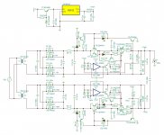
Hi, guys I am also trying to DIY a Jung SR. I have done some modifications to the original design based on some comments and ideas in the forums. I am posting my schematics. Any ideas or suggestions are welcome.
tubeing: I am also using a voltage reference, but I am isolating its power input. I will do a quick compare on the regulators you suggested, since I haven't come along them while in my research phase. In the schematic I am using the ref02 but I am thinking of using the ref102. Also any opinions about the Linear LTZ1000? Also I notice that the opamp you are using is a BJT opamp, I remember some issues on stability reported when using non-FET opamps (like the AD825). So you might want to go back to the original Op Amp or perhaps do some testing on a real circuit and report.
Also I replaced the LM317 for a discrete tracking pre-regulator and added another BJT in parallel to the the D44H11 in order to reduce the output impedance. Some values of the constant current source have been modified, and a transistor at the output of the op amp has been added.
I am thinking on also isolating the power input of the opamp and see if it makes some difference.
So far I have only simulated this circuit and the preliminary results show a very stable response and a ridiculous low noise of 3.8pV!!!! about 40db less than the original design (at least on simulation).
By the way, all 100uF capacitors shown will be bypassed by 100nF Film caps. So another question will be, if it will be a good idea to further bypass using say 1nF in parallel with the 100uF and 100nF caps?
Thanks.
Attachments
Could you explain this please?Kelvin connection of the error amplifier yields a dramatic improvement in output impedance.
Tha AD8027 has protected inputs via integrated diodes. Only for this reason I did not use external diodes. But maybe it's better to place them without mounting them if there's need.It's also a good idea to protect then inputs of the error amp (shown in the 2nd schema.)
Thanks!
Stefano
Why isolating the ref input? I need to go down to 3.3V, I can't use LTZ1000 but if you need more than 7-7.5V I think it could be a good choice.tubeing: I am also using a voltage reference, but I am isolating its power input. I will do a quick compare on the regulators you suggested, since I haven't come along them while in my research phase. In the schematic I am using the ref02 but I am thinking of using the ref102. Also any opinions about the Linear LTZ1000?
Also I notice that the opamp you are using is a BJT opamp, I remember some issues on stability reported when using non-FET opamps (like the AD825). So you might want to go back to the original Op Amp or perhaps do some testing on a real circuit and report.
Same problem as before. I need Vout=3.3V so the opamp must be chose considering this parameter. If you can suggest other opamps with different input stages, high speed, low noise and low supply voltage (down to 2.7V) I'll be happy to try them!
I was wondering about using two pass transistors in parallel but I'd need to modify the driving stage, because the op amp is not able to source all the current needed by the two BJTs.Also I replaced the LM317 for a discrete tracking pre-regulator and added another BJT in parallel to the the D44H11 in order to reduce the output impedance. Some values of the constant current source have been modified, and a transistor at the output of the op amp has been added.
By the way, all 100uF capacitors shown will be bypassed by 100nF Film caps. So another question will be, if it will be a good idea to further bypass using say 1nF in parallel with the 100uF and 100nF caps?
Thanks.
I think it's a good idea to use multiple bypass (most of the time), so you can "cover" a wider frequency range filtering the rail. I use the same idea where I think it can help.
Thanks to you!
Stefano
Could you explain this please?
Stefano
Jan explained it better than me -- it's in part III of their Jung-Didden articles which appeared in The Audio Amateur in 1995 -- they are archived on Walt's website: Home Basically, sensing the voltage at the load, rather than on the regulator PCB means that very little current flows in the "sense" (measurement) part of circuit, thus very low ohmic losses. It's the same principle by which one measures 4-wire resistance on a high quality dvm.
Below is a reproduction of Figure 7 from TAA 3/95:
Attachments
Last edited:
Do you think that replacing a standard linear regulator with this design (in a 3.3V application, where it has to feed a digital board with 2 DSPs and a DAC) I'd notice some improvements in sound? No analog rails, only digital I/O and logic.
Hi tubeing, I still don't understand very well what exactly are you trying to power. This kind of regulators are better suited for Audio applications hence the higher voltage (say 9-20V). Why you want to use it to power a DSP or other digital components?. I am sure there are many specialized regulators at 3.3 for these kind of applications, even switching regulators followed by linear regulators will do perfectly. If your application has digital and analogue parts, then you should split rails and grounds. This will give you the best performance. I guess it can go something like: using a Jung regulator at around 12V to drive an amplifier section, then step this down using a linear regulator (or two in series) to 3.3V.
Regards.
- Status
- This old topic is closed. If you want to reopen this topic, contact a moderator using the "Report Post" button.
- Home
- Amplifiers
- Power Supplies
- My first Jung regulator: help needed