Hi all,
I'm a novice at component level fault finding so be gentle with me!
I have a ONKYO CR-305TX that I've checked the fuses, but it doesnt power up.
I have located the service manual -
Onkyo CR-305TX Service Manual free download,schematics,datasheets,eeprom bins,pcb,repair info for test equipment and electronics
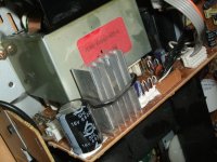
Looking inside at the PSU there is a lot of paste around the bases of some components - is this normal? (see attached photo)
I'm a novice at component level fault finding so be gentle with me!
I have a ONKYO CR-305TX that I've checked the fuses, but it doesnt power up.
I have located the service manual -
Onkyo CR-305TX Service Manual free download,schematics,datasheets,eeprom bins,pcb,repair info for test equipment and electronics
Looking inside at the PSU there is a lot of paste around the bases of some components - is this normal? (see attached photo)
Attachments
Last edited by a moderator:
We could use better, well lit, higher resolution top-down pictures of the boards including power supply board and amp board, but at this point check what I mention below and if that is not helping, if you get output from the PSU board then the amp board is the focus while if you don't get any measurable voltages form the PSU board then it is the focus (for now at least).
Am I correct in thinking that this unit is supposed to have the display turned on at all times, I mean that even in soft-off mode there is "something" on the screen, but that right now as the amp is, there is nothing on the screen at all, no signs of life or power of any kind from the amp, that the CD drive door doesn't open under its own power either?
If so... basically, you'd want to unplug the power supply board from the amp board and any others it is connected to, except if there is a board for the power-on switch, leave that connected for now. Turn the amp on. The next step is very important: Do not electrocute yourself.
With the amp on, measure for DC voltage output on the power supply board connector(s). The service manual shows the following voltages: -27V, +12V, +22V, -22V, +5.6V. I assume you know that you can put your multimeter negative probe on any known ground point while probing for these voltages, and/or to identify the ground leads from the transformer connector if that is not yet obvious visually.
You state you checked the fuses, implying you found more than one. It is late here and my eyes might have overlooked it but I only see one fuse on the block diagram. Actually that is not true, I do see a second fuse but where it is, makes me wonder if you checked it. The transformer seems to have a (probably resettable fuse type but that might have failed unable to reset) fuse which is usually under the tape around the primary windings. Set a multimeter to measure the resistance of the transformer primary windings. If it appear to be an open circuit that fuse has probably blown leaving you to replace the whole transformer OR take the tape off till you see the fuse and can directly measure for continuity at its pins and if it is an open circuit/failed, then replace the fuse.
Before you start tearing apart the transformer, see if the switch works. Unplug the plug to the power switch and use something like a paperclip to connect the contacts in the connector that went to the switch, to complete the circuits the switch would closes as per the block diagram in the service manual. Make SURE you connect that right, so that each transformer lead is going to a separate pin of the bridge rectifier component or subcircuit (meaning 4 diodes), not shorting the two transformer leads together. I apologize if this is already obvious to you, but I mention it because you mentioned you were a novice at fault finding. If it still doesn't turn on and tracing back the power switch wiring to the power supply board shows that there is continuity where you meant to jumper out the switch, we can rule out a switch failure.
Thanks a lot for your comprehensive reply -
yes there should be something on the display at all times and no the CD tray wont open at all. I also tried a reset procedure as mentioned in the manual.
Yep I'm aware I can test those votage levels to any known ground point - and I am an electrician so I know not to electrocute myself (and I'm also aware that the capacitor can still store charge!)
you're right I didnt check the fuse under the transformer tape (only the ply & slow blow fuse on the PSU board) so I'll check that and if its OK the voltages on the output winding
I havent checked the power switch either , so thats worth checking too - thanks
Hello!
Please be prepared for some awkward expressions later here, as English is not my mother tongue. I would be very glad if one of you could give me some good suggestions on how to fix my Onkyo receiver.
I bought the EU version (230VAC, MD terminal section, no sub out) of this unit on a 2nd hand market a couple of days ago.
Everything was working fine until my little son started to play with his model railway on the same safety circuit in the room. It's an old fashioned one back from the 60ies with very basic PSU (in fact transformator with nothing else) and AC drive. However I have a suspicion that switching backlashes might have caused peaks in the mains voltage that killed *something* on the PSU board (U2, NAPS-6878) or even worse the µc board (U8, NAAR-6875) of the receiver.
Symptoms are now:
*) when I plug in the system, not a single sign of life appears. Except one time, when after plugging in a short flicker displaying "--:--" on the front showed up - hardly perceivable. Not any reaction to any button pressed on the front.
*) certain resistance between power cord pins measured - therefore the primary circuit including the two fuses is still functioning.
*) The output voltages come from different windings on secondary side. According to the schematic some of them should be steadily present, others are switched by the µC of the U8 "mainboard". I measured the following (with my cheap multimeter) voltages to GND - refer to the PC board connection diagram of the service manual linked in the initial post of this thread:
JL504B connector:
+B ... 1.0 V
-B ... 0.4 V
P901B connector:
POWAMP ... 0.0 V
POFF ... 4.8 V
+5.6V ... 2.0 V
-VP ... -27.4 V
+12V ... 0.1 V
The voltage between FL1 and FL2 in AC mode was 3.7 V~.
Based on that, can anyone of you give me recommendations what to check next? Thanks in advance!


Different issue - distorted audio
Mine has distorted audio in preamp stage, both channels. See attached schematic portion. Audio is loud and clear going into pin 5 of Q403 & Q405, but pins 6&7 (on both) are extremely low and highly distorted. Thoughts??
Mine has distorted audio in preamp stage, both channels. See attached schematic portion. Audio is loud and clear going into pin 5 of Q403 & Q405, but pins 6&7 (on both) are extremely low and highly distorted. Thoughts??
Attachments
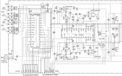
Disconnect one end of C429. Does pin 7 now give signal? Then problem is a short past that point. (But not much there, unless the mice have been storing pennies on the Volume pot lugs.)
Shorted C413, but 100p caps don't short. Also you say both channels? Has to be something common to both.
DC voltages at NJM4565 pins? Decent or dubious?
A dead NJM4565 seems very very unlikely, but if nothing else comes to light, it is going that way. TL072 is probably a fine replacement, just to check and maybe forever. (Wait-- the gyrator at Q403 2-3-1 has a 680r, which is a bit low for TL072, which may be why a NJM4565. Still, audio should pass no-fault when the Loudness(?) feature is not selected, and small-fault when it is.
For purposes of following up on your post, I'm usuing even number (right side) component testing - only because that side is easy to access on the board without requireming me to fully remove the board...
Yes problem is on both channels.
So disconnect C430 shows no change. EXCELLENT debug tip though to cutoff the following part of the circuit. I will file that under "always remember this tip"!
Voltages on NJM4565 are as follows:
Pin 1 13.2V
Pin 2 13.2V
Pin 3 83mv
Pin 4 -133mv
Pin 5 53mv
Pin 6 12.5V
Pin 7 13.1V
Pin 8 13.8V
Some minior variations around those reading depending when I took them, but no more than .5V on the big ones.
- Home
- Amplifiers
- Power Supplies
- Onkyo CR-305TX PSU FAult