Hello all !
I would be very grateful if you help to solve my problem positively.
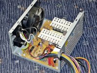
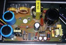
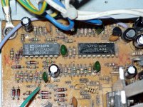
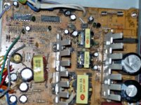
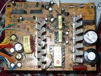
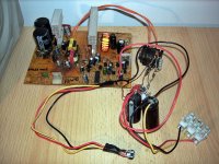
It has the ATX - power supply 500W.
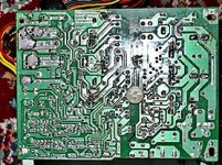
How does this ATX - power supply look you see in the photos!
From him i want to create an symmetrically regulated power supply: + / - 0 to + /-40Vdc?
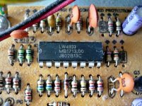
IC it is LW4933 (MB1713.00)
Give help to change to do this for power supply to enable it to deliver the output of Us = + / -0 ....+/- 40Vdc and current from 0...8A.
thanks and cheers
I would be very grateful if you help to solve my problem positively.
It has the ATX - power supply 500W.
How does this ATX - power supply look you see in the photos!
From him i want to create an symmetrically regulated power supply: + / - 0 to + /-40Vdc?
IC it is LW4933 (MB1713.00)
Give help to change to do this for power supply to enable it to deliver the output of Us = + / -0 ....+/- 40Vdc and current from 0...8A.
thanks and cheers
Attachments
Last edited:
Just for starters,You will have to re-wind the transformer,and re-dimension the feedback resistors/circuitry.
(EDIT: and replace the rectifiers/caps with higher voltage parts.)
Then there's likely a power-good/watchdog chip in there on the output side that you'll have to fiddle with,or disable.
(EDIT: and replace the rectifiers/caps with higher voltage parts.)
Then there's likely a power-good/watchdog chip in there on the output side that you'll have to fiddle with,or disable.
There are many tutorials about how to convert ATX PS to lab PS, but I never seen a tutorial how to make a dual PS from this kind of PS.I think this is not possible because it provides maximum 12V and you need to change too many things to make it going to 40V.This IC (LW4933) is a PWM controller and you need at least the datasheet for it, to know what it can do.
You can wire them in series provided you keep them isolated from one another.
Six of them would give you -+36 or 8 of them for +40v.
There is a web site that desribes how to do this.
jer
I prayed to say where is that Web-site?

thanks
I found the link!
This is only one of many descriptions that I have found,But one of the best examples.
You just have to do a little searching.
I will keep searching for a few more in depth info.
Basicaly they all must be isolated from one another and only the mains ground (green) on the bottom supply is connected and the rest are not.
The mains ground (green) is only connected to the ground (black) one the output side.
With the mains connected (Black for hot and White for neutural) in parallel and the outputs in series.
Pretty straight foward.
The cases must be isolated from each other otherwise each sucsessive unit would be shorted thus the reason only bottom mains ground is connected.
As it is shown each case will exhibit the next step up in voltage ( in this case 5V)
Because it is this connection (mains ground (green)) that goes to the cases and must be isolated as the mains are already isolated from the rest of the circuit.
If I were to build one (as I have been planning to), I would take them apart and remount the boards in an insulated case and on some insulated standoff's to insure that no shorts could occur and blow the whole thing up.
The "Tower of Power" - A 30 Volt Computer Power Supply Stack
How to connect computer power supply in series or in parallel?
Last edited:
Here are a few more links to help get you going,just some more info and one is on parallel operation.
Good Luck!!!
jer
Computer Power Supply- ATX PC Pinouts, Schematics, Repair
PC Power supplies in series?
A simple high quality 12Volt 100Amp Power Supply- Part1 - Page 51 - RC Groups
Info: Can I use two Power supplies with one computer?? - Overclock.net - Overclocking.net
PC supply
P.S. Remember when doing this that the maximum current rating is only going to be what the smallest supply can provide, should you use supply's with unequal current ratings.
Last edited:
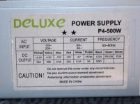
This has been said already above, but it cannot be stressed enough, this thing does not supply 500W, probably not even 200W before it blows.
Sad to say, today there are still many power supplies that are grossly overrated. Particularly those that come free with the chassis.
Sad to say, today there are still many power supplies that are grossly overrated. Particularly those that come free with the chassis.
You must remeber that The wattage rating of a PC Supply is the total wattage and does not mean that a single leg of 5V or 12V can supply that much power.
Although maybe some of the more expensive ones MIGHT be able too, But highly unlikely!
You can only go by the current rating on the label supplied on the case for each voltage leg, But even these are sometimes grossly exagerated, Just read some reviews on them.
You can however modify the output rectifier section to utilize the 5V and 12v Winding sections to get the fullest output capability and there are other sites that describe this as well.
It would be wiser IMHO to use the 5V side as it has the highest current rating(sometimes), In some cases as it depends on the supplies being used.
I wanted to do a 24V supply using two of them for Class A amp project but the ones that I have are only rated for 4.5 amps on the 12V side.
This comes to 54 watts for a 145 watt rated supply and I dont have five of them to reach my goal.
But it is a great concept for some other projects that don't require as much current!
Cheers! jer
Last edited:
Nowadays $50 can get a computer PSU with 25 real amps on +12V. High amperage on 5V is so Pentium III.
And looking much more awesome than that generic gray-box in the first post.
Source
And looking much more awesome than that generic gray-box in the first post.
An externally hosted image should be here but it was not working when we last tested it.
Source
Last edited:
Maybe he's up for a challenge
Yeah you can build your own decent power switching supply from scratch pretty easily. Try some of the National "Simple Switchers", like LM2576 (3A) or LM2796 (5A).
You only need 3-5 external components for the fixed versions, and not too complex of a layout scheme.
Yeah you can build your own decent power switching supply from scratch pretty easily. Try some of the National "Simple Switchers", like LM2576 (3A) or LM2796 (5A).
You only need 3-5 external components for the fixed versions, and not too complex of a layout scheme.
Hi all!
At the beginning to say that this is an excellent forum, since there are many things that I intersuju!
Otherwise I am an amateur elektronics and a great hobbyists!
The other day a friend gave me this power supply from the ATX-300W. The main IC-round with this power supply is TL494.
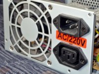
Here are a few photos of the ATX-power supply (Figure 1, Figure 2, Figure 3 and Figure 4).
So please do help so that I create from the power supply with adjustable voltage from 0 ..+/- 40?
The explanation may be that, if gradually, as did professional electronics expert.
Advance thanks for the great help!
cheers
At the beginning to say that this is an excellent forum, since there are many things that I intersuju!
Otherwise I am an amateur elektronics and a great hobbyists!
The other day a friend gave me this power supply from the ATX-300W. The main IC-round with this power supply is TL494.
Here are a few photos of the ATX-power supply (Figure 1, Figure 2, Figure 3 and Figure 4).
So please do help so that I create from the power supply with adjustable voltage from 0 ..+/- 40?
The explanation may be that, if gradually, as did professional electronics expert.
Advance thanks for the great help!
cheers
Attachments
Again, there is no point to this! It will take less time and money too to just cannibalize the PSU boards you have to build a stockpile of parts, THEN use what you have built up if/when it suits the mission specific circuit you want to build.
This topic is insanity. Can't you just accept that the point you are starting from is so far away from your target that there is no value in the parts you are trying to use?
Let me pause and suggest, you are not the first person who had lofty dreams of doing the unreasonable... it is fair, good and just to tell you to avoid this nonsense and so you and everyone else stops wasting time on it.
There is a difference between what is technically possible given an extreme, excessive amount of work and time and expense, and what is reasonable towards a goal. If you were stranded on a deserted island and these were the only parts you had it would be a different story, but obviously they aren't so I think you are either a troll or extremely selfish to ask other people to spend a lot of time to save what is inevitable - buying an appropriate PSU if you want to build an amp, WHICH IS NOT A NECESSITY IN LIFE so spend your time earning money to buy the PSU!
Last edited:
Again, there is no point to this! It will take less time and money too to just cannibalize the PSU boards you have to build a stockpile of parts, THEN use what you have built up if/when it suits the mission specific circuit you want to build.
This topic is insanity. Can't you just accept that the point you are starting from is so far away from your target that there is no value in the parts you are trying to use?
Let me pause and suggest, you are not the first person who had lofty dreams of doing the unreasonable... it is fair, good and just to tell you to avoid this nonsense and so you and everyone else stops wasting time on it.
There is a difference between what is technically possible given an extreme, excessive amount of work and time and expense, and what is reasonable towards a goal. If you were stranded on a deserted island and these were the only parts you had it would be a different story, but obviously they aren't so I think you are either a troll or extremely selfish to ask other people to spend a lot of time to save what is inevitable - buying an appropriate PSU if you want to build an amp, WHICH IS NOT A NECESSITY IN LIFE so spend your time earning money to buy the PSU!
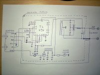
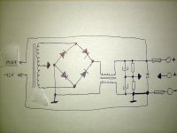
Here's how simple it works!
Transformer should rewind 12V on 80V!
View photos and schematics-1
Now that we've had something to do next to go. In what relationship and wire gauge to rewind the transformer? What do you need to take out the PCB, components, that etc. Give if you can help some more professional people,....
thenks
Attachments

Last edited:
^ Nonsense. Rewinding a transformer for +- 80V, testing, is a ridiculous waste of time.
Schematics? You have no idea what to do and are wasting several hours of our time and your time just to save what? A very minimal amount of money on a transformer? Then, the same thing happens on every single component since you need to change over a dozen?
Sorry, but you are not sane. I am trying to be kind to you and stop wasting other people's time on this earth by suggesting that this is just a foolish idea. On that note, I am done wasting ,my time as I have already given the best advice you could read, any further time is senseless towards the goal unless you just want to learn about electronics in which case some reading or university courses are a better use of time.
Realize, what is technically possible is different from what what is reasonable. What you want to do isn't just unreasonable, it is absurd.
If you can't afford to buy the PSU you need, you should stop wasting other people's time and put the effort into earning money to buy it. It will be cheaper/less time for you to do this, I am trying to help you with this advice. Stop the madness.
Last edited:
- Status
- This old topic is closed. If you want to reopen this topic, contact a moderator using the "Report Post" button.
- Home
- Amplifiers
- Power Supplies
- ATX power supply from 0...+/-40Vdc and 0...8A