Hi guys, I'm trying to design a little PSU for my mini-A.
The whole point of the excersize was the mini part.
The amp is in class A, Dissipates 30W at idle ( +-15V @1A), and can push 10W output. So its by no means one of those big nasty class-a's.
The problem is I am not sure how to interpret the ripple rateing for capacitors.
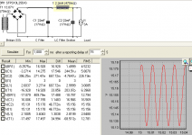
I have done a duncan's PSU plot (attached), now if my eyes are right, it shows 14.27A on C1, but it also shows RMS (5.8A) and mean (-244uA).
Which of these rateings, i.e. max, RMS or mean, do we use to check if a capacitor has an approriate ripple rateing?
It is quite important for me to know, not just for the sake of reliability, but also I am trying to keep the case small (3U), and that rules out alot of the realy high ripple rateing caps, so I wont be able to try something small and then just swap in something big if it fails. I don't want to use snap in caps because they have such short lifespans, add to that the ambient temp will be about 50C on a 25C day...
What causes the big current, the transformer or the capacitor bank/load?
I have found one cap I like and can sorta afford, it is 22000uf ESR at 100Hz is 17m Ohm, but ripple current is rated at just 9.9A.
Will my PSU destroy these caps?
I ordered a thermistor similar to CL60, which I believe can be connected in series between the two 115V primaries (we are on 230V). Will this help?
The transformer specs is as follows incase someone wants to doublecheck my duncan psu calcs.
2x115V to 2x12V.
Primary;
DCR 2x4 ohm rated, measured was 3 point something.
Secondaries 112.5VA each, 9.375A per secondary, 13.07V No load, and DCR 2 x 0.0515 ohm.
The whole point of the excersize was the mini part.
The amp is in class A, Dissipates 30W at idle ( +-15V @1A), and can push 10W output. So its by no means one of those big nasty class-a's.
The problem is I am not sure how to interpret the ripple rateing for capacitors.
I have done a duncan's PSU plot (attached), now if my eyes are right, it shows 14.27A on C1, but it also shows RMS (5.8A) and mean (-244uA).
Which of these rateings, i.e. max, RMS or mean, do we use to check if a capacitor has an approriate ripple rateing?
It is quite important for me to know, not just for the sake of reliability, but also I am trying to keep the case small (3U), and that rules out alot of the realy high ripple rateing caps, so I wont be able to try something small and then just swap in something big if it fails. I don't want to use snap in caps because they have such short lifespans, add to that the ambient temp will be about 50C on a 25C day...
What causes the big current, the transformer or the capacitor bank/load?
I have found one cap I like and can sorta afford, it is 22000uf ESR at 100Hz is 17m Ohm, but ripple current is rated at just 9.9A.
Will my PSU destroy these caps?
I ordered a thermistor similar to CL60, which I believe can be connected in series between the two 115V primaries (we are on 230V). Will this help?
The transformer specs is as follows incase someone wants to doublecheck my duncan psu calcs.
2x115V to 2x12V.
Primary;
DCR 2x4 ohm rated, measured was 3 point something.
Secondaries 112.5VA each, 9.375A per secondary, 13.07V No load, and DCR 2 x 0.0515 ohm.
Attachments
Last edited:
Hi,
For class A you are best off with at the most basic a CRC supply.
Assuming a 1A standing current is both rails its easy to work out
the R voltage drop, 1V for 1R, but 0.22R will still have an effect.
As long as you have decent capacitors don't worry about ripple.
In your application its not an issue, with CRC it becomes less.
0.47R for CRC for both channels seems about right.
rgds, sreten.
Split the total C value for CRC, or make the initial capacitor
slightly higher, e.g. 4,700uF, 1R, 3,300uF for one channel.
The above will be far better than a single 10,000uF.
Last edited:
The ripple current of a transformer is not just dependant on the DCR, the leakage inductance of the transformer and the mains impedance will reduce it somewhat.
To get a real value, power up your transformer measure the output voltage then place a resistive load on it say one or two amps then measure the output voltage. The reduction in voltage divided by the current gives the transformer impedance. This with the DCR can be used to calculate the leakage inductance if you want to be thorough. Or just put the impedance into the simulator as a series resistance in place of the DCR and see what sort of ripple you get.
If the transformer is a toroidal type, consider putting a few more turns of plain hookup wire around the core to give 16V and use a low dropout series pass regulator on each supply rail . Class A amplifiers have poor ripple rejection and need a very quiet power supply, the money saved on two caps should pay for the regulators and heatsink.
The ripple current of a transformer.
Would you please define what that is.
It sounds like the 14.27 amps is the startup transient, the average (mean) will be zero with time. the only current measurement that you need to look at is the RMS current. the capacitor you found rated to 10 amps will work fine.I have done a duncan's PSU plot (attached), now if my eyes are right, it shows 14.27A on C1, but it also shows RMS (5.8A) and mean (-244uA).
Hi, thanks for all the valuable input.
I have been playing around with DPSU2 for 5 days, and have actualy seen some of the thigs you mentioned.
Haveing a smaller cap -R -larger cap produces more of a sawtooth wave than a sine.
Similar thing happens with equal caps seperated bu resistance, with the effect getting worse the higher the impedence between the two caps, I assume this is because the first cap can't charge the second as fast as itself is chargeing.
I also noticed that going from Bridge to R before the first C, reduces the inrush current, I suppose it acts as a bit of a current limiter. in that is increases the impedance seen by the transformer by adding it to the ESR of the cap.
I seem to have found a combo of RCLC that does not exceed the ripple current rateing for the cap I want to use. At 2A I got the 15V point within a few mV and at 3A it drops about half a volt, with the RMS ripple increasing slightly.
My main problem is I don't know what amount of ripple is "good enough" If money and enclosure size was not a problem I could in theory get 1 or 2mv ripple pretty easily with a big fat 5mH choke. Which brings me to another question....
The choke I want to use is a common mode choke, one of those little torroid bobbins with two inductors wound on it... So, the first big question is can I use these in a crc setup, (what if I just use one side of one for a rail?).
From what I have seen in dissasembling (pirateing parts) from dead electronics is that these seem to normally come directly after the mains entry point, so I am not sure if they can be used after the transformer. As far as I understand, in their normal operational mode the two inductors are on the flow and return paths and the inductance (if equal) cancels out along with the noise... i.e. if used like that it doesn't count as an inductor? But still the magnetising currents are too strong to change direction faster than a certain frequency so it acts as a sort of low pass (please correct me if I interpreted this incorrectly).
A common-mode choke is for stopping common-mode signals. PSU ripple is not a common-mode signal. You can use a CM choke as a normal choke by wiring the windings together (series or parallel, to get two different inductance values) but it will not then handle anything like the DC current as the core will saturate. In CM mode the DC currents cancel, but not in normal mode. As a general rule, a CM choke is not suitable for ripple reduction in a CLC supply.
It did sound a bit strange I meant the peak output current of a rectifier circuit as seen by the filter capacitors.Would you please define what that is.
Hi,
You don't generally use a choke first, as it averages voltage,
unlike a capacitor that stores the peak, so generally go CLC.
For the L for Class A its quite simple : wind it to be as high
a value as possible without the core saturating. Note that
the currents in a common mode choke cancel, I don't know
how much current unbalanced your choke can take.
rgds, sreten.
Common mode chokes are rather useless as is. Think low five figures permiability and zero air gap. if you can heat them up and pull the core apart, put in your own gap they will work fine. However, energy is stored as flux squared and because ferrite saturates at a relatively low 0.3 to 0.5T, you really want to use an iron core and run the flux density up as high as is practical, as determined by copper loss and other variables.
- Status
- This old topic is closed. If you want to reopen this topic, contact a moderator using the "Report Post" button.
- Home
- Amplifiers
- Power Supplies
- Help me understand ripple rateing please, I'm stuck.