It will go faster if its not due to some other reason also, like Q103 JFET warming up by radiated heat increasing settle to IDSS. The MKP will not filter the voltage reference noise as good due to much less uF but it has better faster dielectric and a power amp's driver stage has very high signal level in comparison to residual rail noise.
So to go for this PSU's best noise result isn't critical. If it was for an MC phono preamp that the gain is very high and even more in the bass due to RIAA's shape, while the signal is very low, I would have recommended you kept the electrolytic.
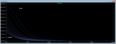
Here is C101's value effect on noise. 10uF to 220uF in 10uF steps. The effect is most noticeable in lower frequencies.
So to go for this PSU's best noise result isn't critical. If it was for an MC phono preamp that the gain is very high and even more in the bass due to RIAA's shape, while the signal is very low, I would have recommended you kept the electrolytic.
Here is C101's value effect on noise. 10uF to 220uF in 10uF steps. The effect is most noticeable in lower frequencies.
Attachments
I understand correctly that if you use high voltages (+ + 35V in my case), I would best use an electrolytic capacitor of 220 mkF instead of 10mkF / MKP? Or does this only apply to the phono preamplifier? I use SSLV for a pre-driver and VAS at a class A amplifier (100W). Thanks a lot for all the detailed answers and I apologize if I asked so many questions.
Higher or lower voltages isn't the matter. Sensitivity of an application to best noise from the reg or tolerance to lesser noise spec is the matter.
There is a voltage reference in the regulator circuit. Its the simplest passive there is. Its called Norton type. Its current dictated by Q103 JFET is converted to voltage by the resistance and Vf of the other components in series above Q103. Its a unity gain Vref i.e. its not a small steady voltage multiplied by a local amplifier but it creates the full Vout without its self noise being multiplied also. So its inherently lower noise in comparison to other solutions, like those active ones that have to multiply an internal low voltage Zener many times so to reach 35V.
This Vref must still be filtered to lower its impedance and its noise further. There is a gamut of capacitance you may use that progressively filters it deeper as demonstrated in the graph I posted.
How quiet you need it to be mainly depends on how sensitive your application is. Say its a VAS and its current sourced so it has a high enough power supply rejection ratio and a very high signal voltage level also. That one would not be judged sensitive to noise. You may very well subjectively prefer the "quickness" and low THD of MKP dielectric there because it will be more prominent than deeper noise filtering.
When you don't have info on an amp's PSRR etc. simply compare subjectively using an electrolytic Vref filter to using an MKP. Because various designs may have unexpected characteristics. The PCB can host both encouraging such versatile decisions.
Some seconds of regulator Vref/Vout heat up/charge up settling time does not look important in the context of a Class A amp that may need half an hour to warm up itself to bias steadiness already.
P.S.
What to also think about or measure in your high voltage swing case that is a priority, is how much peak current the VAS will demand in full swing so that the reg's CCS setting will surely cover it and then try to allow ample spare current on top of that like 200mA or more so the rails will see less IMD. That entails deciding able sinking because at 35V the spare current will create enough heat since Power=I*V.
What to also think about or measure in your high voltage swing case that is a priority, is how much peak current the VAS will demand in full swing so that the reg's CCS setting will surely cover it and then try to allow ample spare current on top of that like 200mA or more so the rails will see less IMD. That entails deciding able sinking because at 35V the spare current will create enough heat since Power=I*V.
 You are welcome. Good luck in this application too and let us know your final decisions and results for it if you may because the readers always benefit more from practical conclusions after a discussion.
I am not the best guy to ask about DAC building practice but I have some friends locally that they are very much into the DAC thing like DimDim and Lemon who do diy boards with many top notch LDOs and still pay much attention to choosing their common 5V rail pre-reg as they tell me.
Thanks Salas, I was just curious.
That does not stop me from working on my new project, which will only be SSLV
Thank you.
Nice. I see REF-D shunts also. Is that Sonny's 4490 DAC & dif pre? I have seen such master regs mix in some Soekris builds by members here also with very good subjective feedback.
Yes, it's Sonny's 4490 DAC + preamp, which is very-very good ")
With him I want to use a Renderer (NMR media renderer interface - electronic, engineering and consulting , which will use a Reflektor-D (3.3V).
Another D-Reflector-D has DAC (5.5V)
An SSLV for I / V (- | + 15V)
An SSLV for the preamp (- \ + 15V)
With him I want to use a Renderer (NMR media renderer interface - electronic, engineering and consulting , which will use a Reflektor-D (3.3V).
Another D-Reflector-D has DAC (5.5V)
An SSLV for I / V (- | + 15V)
An SSLV for the preamp (- \ + 15V)
Last edited:
Merlin BAM Power Supply
I have Merlin BAM (Bass Augmentation Module) that I am considering powering with 2 sets of SSLVV1.1's that I have on hand. The circuit is a very simple filter circuit utilizing 1 AD744JN op-amp per channel. The unit is currently powered by either 4X 9V Nimh batteries or a wall wart supply both feeding typical 7815 type regulators with electrolytic filter caps at the output.
The circuit current draw @+/-15Vdc is very low, Spec for 1xAD744 is 3.5ma Typical and 5.0ma maximum. I would be using 4 separate SSLV1.1'sX 2 set for +/-15Vdc for the left and right channels.
1) Would this be an appropriate use of the SSLV1.1 considering the very low current demand of the AD744's?
2) If so what would be the recommended target constant current for Q101 with an expected current load of 3.5-5.0mA?
3) What size and output voltage transformer would be best? I was considering 18Vac secondary on the transformer with hopes of approximately 25Vdc at the output of the filter cap C105.
Last edited:
Antek AN-0220 for example is just $11 for 25VA and has two separate 20VAC secondary outputs to can feed one SSLV polarity each. Since those regs have own rectification stages they will not share a middle tap and a single bridge, they use the better two bridges & two isolated secondary outputs configuration.
27-30V DC depending on mains voltage which is usually healthier than nominal. But at 100mA CCS its 1.5W dissipation only for the 9610 Mosfet and 15V across makes its internal capacitance lower. So its not an unbearable or bad thing to have some extra input voltage in this situation.
Thank you Salas. Can you make recommendations for the brand of capacitors to use in position C105, C101 and C103? I know this a subjective area but wondering if there is any type/brand that has been shown to be sonically beneficial? Do not mind spending extra on better sonic performance if like Mundorf SGO and such if there is a sonic benefit. The Merlin VSM speakers I am using are very high resolution.
Thanks again so much Salas! What are your thoughts on a flat pack transformer like this one.
LP-40-600 Signal Transformer | Transformers | DigiKey
Verses a straight up torroidal like the Antek AN-0220 that you had mentioned previously? I have seen in other discussion on the board that some prefer the flat packs to the torroid. Your thoughts are greatly appreciated.
LP-40-600 Signal Transformer | Transformers | DigiKey
Verses a straight up torroidal like the Antek AN-0220 that you had mentioned previously? I have seen in other discussion on the board that some prefer the flat packs to the torroid. Your thoughts are greatly appreciated.
- Home
- Amplifiers
- Power Supplies
- SSLV1.1 builds & fairy tales