1. It will do when you will use only 2 terminals representing 12V and half the VA. This is a 12+12V transformer. Better not waste half of it if you can find just a 12V 2 terminal secondary one. Unless you got a use for the spare secondary. You can parallel those secondaries also but the VA rating is already overkill. Rcore is great when magnetic field is an issue and is good for all other specs too. Ei is lower capacitance than toroid, toroid wins Ei for bulk and efficiency in large applications. Not an issue here. I prefer a good Ei in small apps.
2. 300mA is a fine plan.
3. 2x 1.9V Vf Leds + 0.6V Vf 1N4003 diode or alike= 4.4V. Add 0.6V Q304Vbe which is there by default, =5V. Orient diode reversely than PCB printed for D301 Zener using its place. Alternatively a ~220R for R303. If circa 3mA runs it then a 200 Ohm will do 0.6V. Its all about what Q303 IDSS you got when installed. You measure the output and you trim the final value. Just one Led and a trimmer is for skipping calcs and fixes but not as perfect for ppm and robustness.
4. Use good resistor. A plain one won't kill it but a good one is superior ppm.
5. Don't know the sensitivity of your circuit for lowest freq noise, that would take an on hand analysis with a lab spectrum analyzer. Use 470uF to be on the safe side.
6. More than enough.
Nothing much, keep diying.
1. But will it cause any problems in terms of excess heat? I can't find any non-2x12/15v EI..You can parallel those secondaries also but the VA rating is already overkill.
2. I see. Is 0.6V referring to the forward voltage? I can't seem to find any 1N4003 with 0.6V. I don't suppose the diodes i have now will work, right?3. 2x 1.9V Vf Leds + 0.6V Vf 1N4003 diode or alike= 4.4V. Add 0.6V Q304Vbe which is there by default, =5V. Orient diode reversely than PCB printed for D301 Zener using its place. Alternatively a ~220R for R303. If circa 3mA runs it then a 200 Ohm will do 0.6V. Its all about what Q303 IDSS you got when installed. You measure the output and you trim the final value. Just one Led and a trimmer is for skipping calcs and fixes but not as perfect for ppm and robustness.
Thanks again!

All the 1n400x diodes have a voltage drop around 600mVf.
The exact voltage drop varies witht he current that is passing at any instant.
At very low currents the Vf could be around 400mVf
At very high currents (transient not continuous) the Vf could exceed 1000mVf.
At our "normal currents" of 10mA to 300mA expect diode drop to be between 600mVf and 700mVf.
Look at a datasheet. You will see how Vf varies with Id and with temperature.
BTW,
Rapidonline will sell you 1A diodes for about £2 per 100.
1. But will it cause any problems in terms of excess heat? I can't find any non-2x12/15v EI..
2. I see. Is 0.6V referring to the forward voltage? I can't seem to find any 1N4003 with 0.6V. I don't suppose the diodes i have now will work, right?
Thanks again!
1. No. Paralleling same spec secondaries just makes a double secondary transfo fully potent for VA in just one secondary. This is for when needing the grunt and having a small transfo though. Better leave it spare in this case, you may find a use for another reg or something else.
2. There is a chart for Vf VS forward current. At 10mA those 4003s are 0.6V, here it will be even less current running, so you get bit less than 0.6V possibly.
The Schottky you got don't show chart below 100mA, such are low Vf anyway, if they will be say 0.3V in our circuit you will need two. You can test that by using a 2SK117GR as CCS to feed your leds and diodes in a string to avoid soldering and de-soldering. Hook drain on a 9V battery plus, tie gate and source together and from there insert your reference string to battery minus. Measure the drop across the leds and diode(s) string, change something if not about 4.4V, and when OK install those. Install that particular 117 as Q303 also.
Why you would need a 63V filter capacitor in a 12 VAC rectified input reg? 25V cap is the right one.
I should be thinking more. A LOT more. Salas to the rescue again!! 
Where's everyone getting their 4700 uF/63 Panasonic FC and Nichicon Muse from? Having trouble trying to get those values. Can only find FC in 4700 uF/25V
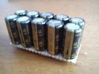
Better put 10 caps in paralel 470uF Pana FM
Where's everyone getting their 4700 uF/63 Panasonic FC and Nichicon Muse from? Having trouble trying to get those values. Can only find FC in 4700 uF/25V
Well, in case you really do need 63v one's, here is the one's I am using in BIB feeding Salas Simple RIAA pre.
ECO-S1JA472CA Panasonic Electronic Components | Mouser
No worries, I do worse all the time. Its just a hobby.
Indeed dear watson
Real scaryBetter put 10 caps in paralel 470uF Pana FM
Thanks for sharing, Tea-Bag! I went with a 4700/25 in the endWell, in case you really do need 63v one's, here is the one's I am using in BIB feeding Salas Simple RIAA pre.
ECO-S1JA472CA Panasonic Electronic Components | Mouser
I hope i got it right..3. Use a diode in same orientation as the ''see text'' PCB area Leds. It will give you a voltage drop that will be self set, when with a resistor it will depend enough on Q303's Idss that energizes the Leds. Its either you use 1k trimmer and one red led, or 2 red leds and a diode for 5V. The diode position can alternatively be a ~220R for easier filtration by C301 but it may give you hassle trimming it is the deal. Its a small chance it will be grossly off target with a 220R though. Don't go after 5V dead on, go after you are in your client circuit's acceptable power voltage area.
An externally hosted image should be here but it was not working when we last tested it.
Also, regarding the use of powercon connectors, I'm not too sure about the polarity. Is this correct?
NAC3MPB goes to +F +S 0 0 of regulator; and
An externally hosted image should be here but it was not working when we last tested it.
An externally hosted image should be here but it was not working when we last tested it.
Is it worthwhile to DIY a better usb cable? The current cables' wires look quite fragile and i don't know if it has any impact on power delivery.. How difficult it is to DIY a usb cable given that one end is a usb mini b, soldering seems to be quite a challenge?
Last edited:
No, reverse the diode. You put it in as a Zener now. Missing C301 also, but you know that.
About USB splicing, it does not look like a nice job. Bit of a bodge. Is there a way to isolate the USB power lines at the DAC PCB by cutting some vias and feed the power nodes from the reg there?
NAC3FCB is a 3 terminal AC power connector. You need 4 contacts of far lower rating. Those cheapo CB microphone ones with securing ring will do. Never turn on before the connector is fixed to load or dummy resistor terminated for any lone PSU testing, else the sense and force circuit will be non complete. Don't know at 5V, but higher there had been damages.
Real scary
Thanks for sharing, Tea-Bag! I went with a 4700/25 in the end
I hope i got it right..
An externally hosted image should be here but it was not working when we last tested it.
Also, regarding the use of powercon connectors, I'm not too sure about the polarity. Is this correct?
NAC3MPB goes to +F +S 0 0 of regulator; and
An externally hosted image should be here but it was not working when we last tested it.
An externally hosted image should be here but it was not working when we last tested it.
Is it worthwhile to DIY a better usb cable? The current cables' wires look quite fragile and i don't know if it has any impact on power delivery.. How difficult it is to DIY a usb cable given that one end is a usb mini b, soldering seems to be quite a challenge?
Not too difficult
Attachments
Nichicon KG - known as "Gold Tone" - also, "Elna for Audio" type, similar sound to the "Starget" caps, not the same as Silmic or Cerafines.
I like Nichicon KG Gold Tune & prefer vs Elna.
An externally hosted image should be here but it was not working when we last tested it.
I have no experience cutting vias and afraid i'll botch it up
Are there any other practical alternatives?Regarding the 4 contacts CB microphone connector, is this fine?
Will a 12R 3W work for dummy load?
- Home
- Amplifiers
- Power Supplies
- SSLV1.1 builds & fairy tales