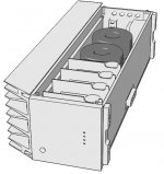
Very nice housing plan. With many high current regs in there, semis have a Tc, passives have a Tc, you should expect some cold-hot drift even with stiffest Vref choices. One good thing in this reg is that its normally a negative small drift. Thus safer than an escalating Vo. Remember to show us your build when finished. People are keen for cool ideas.
Box should be finished this weekend, regulators will follow.
There will be a mirror module on other side of box with Ni-MH cells and charger for the IV ( EUVL 's SEN ).
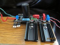
I was actually expecting the sink to get at least warm but it's completely cool even with your regulator at full load for 2 days !!! so i guess i can put another 2 there easy.
There will be a mirror module on other side of box with Ni-MH cells and charger for the IV ( EUVL 's SEN ).
I was actually expecting the sink to get at least warm but it's completely cool even with your regulator at full load for 2 days !!! so i guess i can put another 2 there easy.
Best case 188F=87C. Junction to case is 1.7C/W in that semi (IR datasheet), so you are at 100C junction temp for say 5W. (Meltdown @ usually around 175C). Either you got a very small sink for that setting, or you are using a dummy load that isn't simulating as strong current draw as the destination load's average and too much is burned on the Mosfet. Your voltage setting and dummy load value please? Also some info about your sink (C/W) or photo?
Go Advanced under reply messages, there is upload pics menu. Make it say 1024X768 first.
Something here does not compute. If you got 1A CCS setting and a 5.5R dummy, then 0.9A should have gone to the dummy @ 5V. The output Mosfet should dissipate only 0.1A*5V=0.5W. But yours is suspiciously hot. Maybe you run much higher CCS? You will know by voltage across the CCS setting resistor divided by its value. Is the dummy hot at all?
Something here does not compute. If you got 1A CCS setting and a 5.5R dummy, then 0.9A should have gone to the dummy @ 5V. The output Mosfet should dissipate only 0.1A*5V=0.5W. But yours is suspiciously hot. Maybe you run much higher CCS? You will know by voltage across the CCS setting resistor divided by its value. Is the dummy hot at all?
- Home
- Amplifiers
- Power Supplies
- SSLV1.1 builds & fairy tales