Idss is a device parameter.
Id is the device operating current.
They are not the same.
If one builds a B1 or a DCB1, one chooses to run the two devices at an Id that happens to be the same value as the Idss, if one can keep the Tj at the specified 25ºC.
In this regulator we select a device with a certain Idss. That is not the same as the operating current Id.
The BC550 contributes 0.6V, the 1N4007 you used another 0.6V, the rest is all the resistance you got in series times your associated K117 current. If the things don't add up normally for K117GR IDSS range then there is something wrong with it.
Is Q103 the jFET with 0.6mV across D to S?
If that is so, then the Idss of 4.3mA measured at 10Vds will be much different from Id when 0.6Vds is applied.
Expect Id ~ 50%Idss, i.e. around 2mA to 2.5mA.
The output voltage will be Vbe of the BJT plus the Voltage across the Vref string.
The Voltage across that Vref string will be due to the Id passing that jFET of about 2mA to 2.5mA.
If the Vref string were a diode + a Zener (5.6V) + fixed resistor (1k0) then the voltage drop due to 2mA of current flow is ~ 600mV for diode + 5.6V for Zener (if Pz >10% of Pmax) + 0.002 * 1000 ~= 8.2V
One can short out (link across) or add as many components to the Vref string as needed, to get the desired Vout.
Just measure the in circuit Id of the jFET by measuring the voltage drop across the fixed resistor. That resistor can be 10r. 2mA and 10r would read ~20.0mVdc using a 199.9Vdc scale of a dmm, good enough accuracy for our purpose.
It really is that simple, some simple arithmetic combined with an understanding of what the circuit is doing.
Voltage drop across Vref resistor (11R78) 3,20V + 0,6V diode + 0.002 * 1000 = 5.8V but I get Vout 5.23?
What is the measured voltage across the fixed resistor?
What is the value of the fixed resistor? Or if it's a parallel pair, what are the values?
From there you get the actual current passing and can use that to substitute for the 0.002 value that I guessed at for a 4.3mA Idss running @ 600mVds.
What is the actual diode Vdrop (Vf)?
I don't understand the 11r78 giving 3.2V for Vdrop. That indicates ~270mA of current flow through the Vref string. That can't be right !
What is the measured voltage across the fixed resistor? Now after 1 hour of warm up 3.14VWhat is the value of the fixed resistor? 11R78 Or if it's a parallel pair, what are the values? 22R+33R in series paralleled with 15RFrom there you get the actual current passing and can use that to substitute for the 0.002 value that I guessed at for a 4.3mA Idss running @ 600mVds.
What is the actual diode Vdrop (Vf)? 0.76V
I don't understand the 11r78 giving 3.2V for Vdrop. That indicates ~270mA of current flow through the Vref string. That can't be right !
Last edited:
............I don't understand the 11r78 giving 3.2V for Vdrop. That indicates ~270mA of current flow through the Vref string. That can't be right !
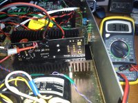
it still can't be right.AndrewT see attached pic.
How can 270mA flow through the Vref string?
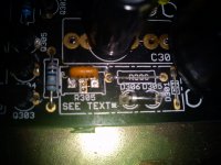
Merlin, you are perplexing Andrew, you have the diode stuffed with cathode going to Q303 and you have it drawn like the optional Zener. Use your DMM and see if you got any short after soldering, especially from Q303's drain to ground. Its impossible to have such high current in the Vref if there isn't an error somewhere.
")
- Home
- Amplifiers
- Power Supplies
- SSLV1.1 builds & fairy tales