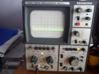
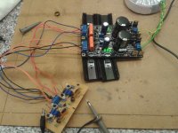
Still problematic.
Merlin, do you have 270R for sure in gate stopper place (parallel on board near the input & output Mosfet pins)? Or something different value by any mistake? Some used before heated cap many times with iron? Because you should have simple line like in your positive pic no problem at least with dummy test.
Merlin, do you have 270R for sure in gate stopper place (parallel on board near the input & output Mosfet pins)? Or something different value by any mistake? Some used before heated cap many times with iron? Because you should have simple line like in your positive pic no problem at least with dummy test.
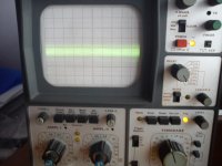
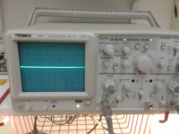
Just did a quick test on a JC2 pre I am doing some tests with.
Negative supply is a flat line with a 20MHz scope set to max.
Probably something is wrong with a resistor, as Salas mentioned. I shouldn' t look at the caps.
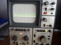
Negative supply is a flat line with a 20MHz scope set to max.
Probably something is wrong with a resistor, as Salas mentioned. I shouldn' t look at the caps.
Attachments
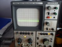
Still problematic.
Merlin, do you have 270R for sure in gate stopper place (parallel on board near the input & output Mosfet pins)? Or something different value by any mistake? Some used before heated cap many times with iron? Because you should have simple line like in your positive pic no problem at least with dummy test.
Measured all four gate resistors 270R in the negative rail and all four measure 270R, attached pic right channel negative rail
Attachments
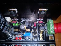
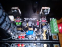
Measured with DMM rest of resistors and are ok in both negative regs, R208 47R & R204 1R
Transistors, Jfets, inspected for proper type proper place odd mistake too?
- Home
- Amplifiers
- Power Supplies
- SSLV1.1 builds & fairy tales