Thanks Salas, I need to find some then.
If you don't find ask Tea-Bag
Extracted from BiB guide Rev.2:
"You could use instead a Zener based configuration. Will give a fixed low drift voltage setting. Add R303 220R 1/4W to aid noise filtering, jumper the LEDs and the trimmer positions. Use 220uF C302 50V. Not an MKT. Zeners need more filtering. There will be additional 0.6V from Q304 Vbe and R303's Voltage drop. VR303=R303*IQ303. Factor in the extra voltages. Q303 JFET will be weaker for IDSS in circuit from what you had measured with a 9V battery. A circa 4mA IDSS 9V testing JFET gives you around 3mA. If you still want keep the LEDs for indication, they will be adding their Vf too as in the first example. The higher the target Vout the more reliable a Zener reference is for low drift VS a resistor reference."
My question is: wich is the minimum high target Vout to use Zener? Zener 0.5W wich voltage? If trimmer is jumped how adjust the Vout? I ask because I'm doing regs. for 30 Vout.
Last edited:
the zener is noisier, but has a fixed voltage that is possible to be higher and possibly more stable than the largest possible total of the series LEDs on the board, so you can avoid the trimmer.
so for your total add the 1.3v drop from vbe + total drop from the LEDs + the drop from the 220r on the zeners tail for the total reference voltage
is that about right salas?
so for your total add the 1.3v drop from vbe + total drop from the LEDs + the drop from the 220r on the zeners tail for the total reference voltage
is that about right salas?
Salas
can we use SSLV1.1 for digital power supply DACs
what do you think about John Svenson simple regulator http://www.diyhifi.org/forums/viewt...n&sid=b9ca21a6f1ce3b6788a41ecd33228a0f#p30415
can we use SSLV1.1 for digital power supply DACs
what do you think about John Svenson simple regulator http://www.diyhifi.org/forums/viewt...n&sid=b9ca21a6f1ce3b6788a41ecd33228a0f#p30415
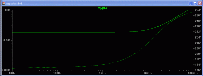
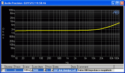
Its been measured on AudioPrecision equipment by member JackInNJ and posted in the general shunt regs thread. Here it is again. Non hot rod & Mosfet output. Matches the simulator in low band and betters it higher. Same settings, no higher than 0.1Meg test unfortunately.
Attachments
Fail
Hi All,
Initial power up fail - I didn't have confidence in my initial population of the board, so I'd like to confirm correct componentry for the following load... The reasoning behind it all would be grand as well.
70ma load per rail @ +\- 15V with a proposed 120ma total through the shunt reg. Transfo is 2x15v 30va
recommended parts? And thank you all for the assist.
Will be better if you use 2x18V, 2x15V works but is better have more voltage against mains fluctuations. 30VA is enough for a total of 120mA, whats the load consumption: 70mA per rail? Salas regs. works better if regulators are set X2 or x3 the consumption, in your case 70mA X 3 times = 210mA , don't worry your 30VA tx can supply. Have you read Salas BiB guide Rev2, is all in the manual?
18Vac might be a bit low for a regulated 15Vdc on the output.
We have been using 15Vac for 10Vdc regulated in the DCB1. 12Vac was not able to drive the CCS properly.
30VA 18Vac+18Vac has a maximum continuous AC current output of 833mAac
The maximum continuous DC current available after the capacitor input filter is ~416mAdc, this depends on the manufacturer's de-rating for this duty.
For reliable and cool operation I suggest the continuous DC current (to feed a Salas style regulator) is <=210mAdc.
That is the CCS limit for a 30VA 18+18Vac transformer. If you adopt a 20+20Vac transformer then the DC current capability is slightly lower, <=188mAdc.
Last edited:
- Home
- Amplifiers
- Power Supplies
- SSLV1.1 builds & fairy tales

