I'm also planning for this use of the BiB.I'm putting together a split rail -25V-0-+25V for the BA-3 front end which draws per channel 50mA.
I'll go for a 23Vac output per secondary winding rated at 500mA. This should account for voltage drop acrss diodes and headroom for the regulator.
I might as well go for the 3.9 ohm 5W R101 (overkill here perhaps).
10000uF 63V on C105.
Dummy load should be 500ohms for each of the rails at 3W.
Comments please.
Chris
Which components have you chosen to set the voltage?
I'm planning for a more reasonable current draw (say 200 mA) to limit dissipation, but I still have to estimate the best combinations of LED's and R101 for this draw at this voltage.
Will you be using plastic or electrolytic filter caps for the BiB in this application?
Cheers,
Nic
I'll go for the polypropylene 4.7uF caps 63V WIMA MKS4 at C102,C202 and at the output C103 and 203. I've already used these and they sound great.
5K trimmer with R103 R203 1.8Kohm and two red LEDs.
Unless Salas tells me different.
It may be that I should go for 8.2 ohms for R101, R301 and three green LEDs.
Chris
5K trimmer with R103 R203 1.8Kohm and two red LEDs.
Unless Salas tells me different.
It may be that I should go for 8.2 ohms for R101, R301 and three green LEDs.
Chris
I'm planning for a more reasonable current draw (say 200 mA) to limit dissipation, but I still have to estimate the best combinations of LED's and R101 for this draw at this voltage.
Cheers,
Nic
Salas suggests adding 150mA to your current draw needs so you are up to 350mA. Look that up on the graph above and you will get a Vgs of about 5V.
If you have about 1.9V drop across the three green LEDs you have a total drop of 5.7V. Voltage across the R101 is 5.7-5=0.7. I=V/R so 0.7/3.9=179mA. If you add another LED though it will be 2.6/3.9=666mA.
Chris
BA-3 front-end draw = 50 mA + 150 mA spare current = 200 mA total currentSalas suggests adding 150mA to your current draw needs so you are up to 350mA. Look that up on the graph above and you will get a Vgs of about 5V.
If you have about 1.9V drop across the three green LEDs you have a total drop of 5.7V. Voltage across the R101 is 5.7-5=0.7. I=V/R so 0.7/3.9=179mA. If you add another LED though it will be 2.6/3.9=666mA.
Chris
3x green LEDs = 6.3V - (Vgs @ 0.2A = 4.2V) = 2.1V => R=2.1V/0.2A = 10.5R
My green LEDs are 2.1V while the red and yellow are very similar and both 1.9V.....
Cheers,
Nic
It's another of my guesses, but 30+30Vac seems better for +-25Vdc.I'm putting together a split rail -25V-0-+25V for the BA-3 front end which draws per channel 50mA.
I'll go for a 23Vac output per secondary winding rated at 500mA.
Yes - as I do not have an output stage readyAre you mounting the BA-3 front end in a separate chassis?
Chris

I will actually be doing a balanced BA-3 (BBA-3) as all the rest of my system is balanced.
In place of these approximations for choosing the right R101 et al. I will get myself a couple of 3W 20R "trim-pots" to experimentally determine the right value for R101
As a balanced load is easy on the supplies I may even reduce the shunt current further - in fact using a shunt regulator is probably an overshoot. Does the, already minimal, BiB noise go up or down with increased current?
Cheers,
Nic
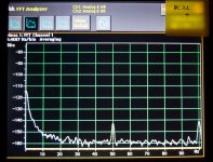
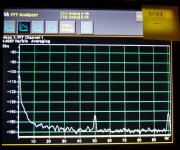
Use at least 100mA more than your load demand, its for keeping the output impedance of the regs low. The more the spare current, the more subtly dynamic the result will be. Precision in the set current isn't much of a concern when there is much to spare. Regarding noise, that comes from the voltage creating shunt part more so than from the constant current feeding part. Since such a reg was not worsening the noise floor of phono stages, I don't think there is a noise concern in the power amp driver stage signal level. Use 220uF electrolytic capacitor in the voltage set rectangular frame section to filter noise better as discussed in the guide, if a priority. Here is an analyzer result for PSU noise in a next of kin Mezmerize DCB1 supply with just 100uF filtering, to have an idea of the noise scale such a topology is capable of. Thanks to Spanish member Ramallo. The rails are AC coupled to the lab grade audio analyzer's input. You can see the hum peaks at 50Hz & 100Hz above the reg's noise floor in the full preamp layout and connections, and the rise in the flicker noise region towards 0Hz (including analyzer's own). 1/f (flicker) is strongly further suppressed with up to 1000uF if for digital clocks where it counts more. But won't help the tone for full range audio IMHO.
Attachments
Salas,
Being a genetic engineer I'm here to learn - and I'm learning. Thanks!
To stay on topic. I think that I have learned that the spare current keeps the output impedance low - which is of course a good thing. However, my ignorance (or curiosity) prompt an obvious next question: is there an important/significant correlation between how low the output impedance gets and the spare current? Or does it saturate at say +100 mA? I.e. Is +200 mA or +300 mA better than +100 mA?
I know that the precision of the exact absolute value of the spare current is not important, but as I'm a scientist, I like the experimental approach of determining which value yield what I asked for!
I also learned that for low noise apps I better filter the voltage setting circuit with a higher capacitance to reduce regulator derived noise (as described in the manual - that I did read 5-10 times!).
Efharistò!
Nic
P.S. I'm closely watching the events in your country to prepare myself for what we have to expect here in the future!
Yes, we are the in vitro test.
Anyway, diehard hot-rod users have used up to 500mA spare, claiming subjective gains in DCB1. They were enough, so I issued the Hypno hot-rod blue. Just judge in your application your own law of diminishing returns red line considering waste heat and electricity bill VS any subjective gains that YOU can assure.
Anyway, diehard hot-rod users have used up to 500mA spare, claiming subjective gains in DCB1. They were enough, so I issued the Hypno hot-rod blue. Just judge in your application your own law of diminishing returns red line considering waste heat and electricity bill VS any subjective gains that YOU can assure.
No, no. True in vivo - experimentation on living human beings!Yes, we are the in vitro test.
I wish you don't have the same problems with "black-block" trouble makers as here in Italy..
Anyway - I think I will opt for a modest current dump as I do not like extremist approaches
Ciao,
Nic
I have done 1 test: with 6.3Vac (75VA) trans vs 9Vac (20VA) trans, for same output of 3.3Vdc with 130mA CCS. At first I think the result should be the same since the output is the same but after a few AB swap (everything remain the same on BiB except adjust the trimmer to get 3.3Vdc), I concluded I prefer 9Vac (20VA) trans. I don't have a scope to measure, I only have my ear to listen. Does anyone have any experience like this with some measurement?
measure the voltage across the CCS to identify what difference there is with the two different transformers.
Supply each transformer from a Variac, setting the voltage fed in to the minimum specified by your supplier.
Measure again the CCS voltage. Do any of these CCS voltages give you cause for concern?
Your ears, no matter how good, and your brain, no matter how advanced, cannot match measurement information across the CCS.
We are into Audio yes?
Then what it sounds like is the best measurement, if it measures great and sounds like crap, is it enjoyable?
Measurements are important for safety and longevity agreed, but the sound is subjective, if it sounds better with an EI Trans, which doesn't shock me- boorah!
If it sounds great, but is safe and measures bad, dilligaf to the measurements.
The CCS must have an adequate voltage drop during all modes of operation.
Listening cannot match measurement for this assessment.
Read my post and learn from it.
We have to ensure the circuit is within it's operating window before making any sound quality assessment.
If the circuit is not within it's operating window then all sound comparisons are, to put it simply, NOT VALID
- Home
- Amplifiers
- Power Supplies
- SSLV1.1 builds & fairy tales