Using the 4 kelvin wire gives freedom in distance and keeps impedance low, the lenghts you use are no problem for the BiB. Sense is often signal wire and force thick wire, that gives unequal Ohm value, does for I know not matter in Salas his schematic. So the difference in length -to the output of the board- you describe =difference in resistance shouln't be a problem. Direct mounting on components could cause instability.
Erik
Erik
Have used to excel sheet to get component values for my two regs. One for Buffalo III (5.25V 440mA) and one for Ian's FIFO (6V 600mA). I posted screenshots from excel below. It would be great if someone could double check to see if it looks ok?
Attachments
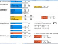
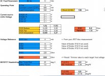
I think they are logical. But do confirm that you get 2.1V and 1.9V from your greens and reds at say 3mA so to be nearer on target. If you will join gate and source on a K117GR and take that node to (-) of a 9V battery, put a led between drain and B(+). Measure the drop across it as it lights up.
P.S. If you don't get 2.1 or 1.9 don't go looking for leds, just feed the real @ working current vf values in the calc.")
P.S. If you don't get 2.1 or 1.9 don't go looking for leds, just feed the real @ working current vf values in the calc.
I feel i might go wayyyy too much into irrelevant details, but nevertheless:
I noticed that the wires to the sensing-circuit is about an inch, while the route from the output-zobel-filter is only half an inch. Normally adding, lets say 4 inch wire, would make this difference insignificant.
But i am placing the Bib's less than half an inch from a DAC, meaning the sense wire will be about 40% longer ... And i really noticed how wire length matters A LOT for output impedance on high frequency (for digital)
Does it make sense at all to mount wires instead directly to:
sense: Q104/105
Force: R107/C104
to be able to make it similar length, for force/sense?
Or is it just wayy too late here in DK, and my interest in my hobby has reached pathological proportions?!?
Looking to take the pcb routes to connector out? Could do if skipping the connector and soldering at the semis pads. Bit of messy looking and I don't know if it would present some benefit since the vias are extensions to the wires themselves. More impedance uniformity maybe by not changing transmission characteristics in a very short 4 wire situation, less joints & screws. Dissimilar length or resistance are taken care of Mr. Kelvin. The gist is IF you can aurally sense it, why not?
I think they are logical. But do confirm that you get 2.1V and 1.9V from your greens and reds at say 3mA so to be nearer on target. If you will join gate and source on a K117GR and take that node to (-) of a 9V battery, put a led between drain and B(+). Measure the drop across it as it lights up.
P.S. If you don't get 2.1 or 1.9 don't go looking for leds, just feed the real @ working current vf values in the calc.
Thanks Salas, I will do so.
Salas
would you please tell us your choice for Vref filter cap
I wonder If obbligato 4,7 - 10 uF at that position Is upgrade over BG N 47 uF
there are lot of obbligato caps gold, premium black, PPE, PA - anyone explain please differences
I found great improvements by using obbligato gold 10u instead of BG47u for vref but that depends on what you are powering with the shunt and also on the type of vref you use.
Line level
Analogue
Prefer the film 10u cap over the BG 47u in this case.
Salas
would you please tell us your choice for Vref filter cap
I wonder If obbligato 4,7 - 10 uF at that position Is upgrade over BG N 47 uF
there are lot of obbligato caps gold, premium black, PPE, PA - anyone explain please differences
Line level
Analogue
For line level and analog you can use film for Vref cap, if you have space better 10uF than 4,7uF.
Prefer the film 10u cap over the BG 47u in this case.
I told you samoloko
Large caps
Merlin: I have been noting your use of large film caps for Vref filtering (for an anlog circuit) for awhile now. I understand that you subjectively prefer the performance with them, and am interested in experimenting with this approach myself. I am somewhat concerned though, with the long leads (antennas) which large caps like these will have. Do you have a 'scope (I do not) and, if so, have you looked to see if these long leads might be picking up and RF and introducing it into the circuit? I assume you have not "heard" any problems which you could attribute to RF, like coarse sounding, or extra crisp HF representation, right?
Does anyone else have experience using large caps with long leads in these positions, and thoughts or advice on whether RF pickup might be a valid concern?
@barrows
I use 10uF 400V Auricap Vref for Legato and scope sowed a straight line without any kind of ripple, the Auricap don't use solid core & the cable is insulated so no problem to make any kind of contact with other components but if you use cap with solid core I will insulated with teflon tube to avoid contacts. Other good and cheap solution is use box caps MKP exactly the same pins distance that have the reg and bypass with small teflon in the other side of the pcbo (can be used for lytic Vref cap when using MC or digital).
I use 10uF 400V Auricap Vref for Legato and scope sowed a straight line without any kind of ripple, the Auricap don't use solid core & the cable is insulated so no problem to make any kind of contact with other components but if you use cap with solid core I will insulated with teflon tube to avoid contacts. Other good and cheap solution is use box caps MKP exactly the same pins distance that have the reg and bypass with small teflon in the other side of the pcbo (can be used for lytic Vref cap when using MC or digital).
- Home
- Amplifiers
- Power Supplies
- SSLV1.1 builds & fairy tales