Hello.
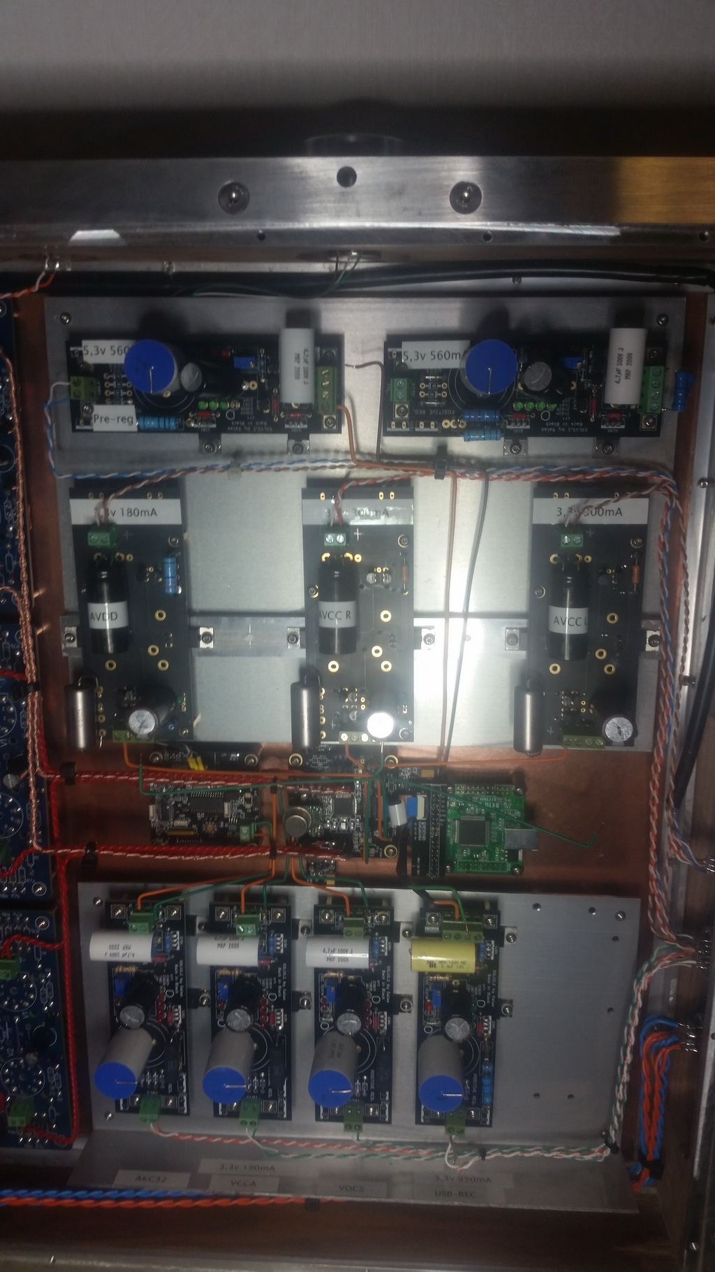
I'm setting up an "Ackodac" with reflektors and bib's and I am wondering if 200uf
will be a problem for a bib ? Thats what I get as capasitive load for the bib that
will work as a preregulator for 3 of "Ackos" 1,2v regulators. If so the usb-reciver
might be a problem as well or ? (100uf).
I'm setting up an "Ackodac" with reflektors and bib's and I am wondering if 200uf
will be a problem for a bib ? Thats what I get as capasitive load for the bib that
will work as a preregulator for 3 of "Ackos" 1,2v regulators. If so the usb-reciver
might be a problem as well or ? (100uf).
Last edited:
You are right there are no sense wires involved here. Lets say just for sake of argument that the regulator feading the acko-regulators is oscillating just a bit due to the fairly high capasitive load. Wouldn't the next (Acko 1,2v) regulator take care of that ? If I'm not misstaken the use of a higher value capasitor (220uf) in the c101 position makes the bib-regulator less prone to oscillate due to a high capasative load, right ? 
It does not tend to oscillate due to a high capacitive load. To the contrary big capacitors at the load narrow the open loop gain bandwidth of the reg. There are scenarios involving long enough sense wires with inductance that can create a peak with low ESR capacitors or gather EMI due to wide area. But sense is not used in your case. The c101 cap does voltage reference filtering only, it is not part of the error amplifier and output circuit.
To really answer and remedy any possible hypothesis it takes an oscilloscope so to actually "see" the rails in any physically different build.
To really answer and remedy any possible hypothesis it takes an oscilloscope so to actually "see" the rails in any physically different build.
")
Merry Christmas to everyone
I'm building a new Shunt Reg for a first stage of a Power Amp after a long time from my last SLV build for a preamp so I need to refresh my study on the calculations for the right current/voltage settings
I see that the on the SSLV1.1 Excel Calculator the Vfs for DX02-DX04 (Current source) are proportional to the R101 value. Is there any meaning to keep resistor as low as possible , isntead of using higher Vf LEDs (ie Green) and use a higher R101 value?
What is preferable to use higher Vfs and higher R101 or lower Vfs and lower R101?
The recommendation for DX02-DX04 are Green Leds (higher Vf) but with relatively lower IDSS fet for the QX02 position (relative to QX03, QX05 positions , according to appendix 5)
Last edited:
Merry Christmas!
I have few quesions:
1. May I use K880GR in SSLV1.1 ? because difficult to get real K117GR now.
2. If I use K880GR, the other components value (resistors, capacitors) will remain unchanged?
3. I need +/-5V output voltage, BJT or MOSFET should I use for Q106 and Q206 ?
4. I just wanted to verify the GDS and BCE pin of Q102,Q106,Q202,Q203 and Q206. I mark the pin in the attached circuit, is that correct?
Thank you.
Attachments
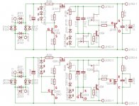
Are Q101 and Q106 both Pchannel mosFETs?Merry Christmas!
I have few quesions:
1. May I use K880GR in SSLV1.1 ? because difficult to get real K117GR now.
2. If I use K880GR, the other components value (resistors, capacitors) will remain unchanged?
3. I need +/-5V output voltage, BJT or MOSFET should I use for Q106 and Q206 ?
4. I just wanted to verify the GDS and BCE pin of Q102,Q106,Q202,Q203 and Q206. I mark the pin in the attached circuit, is that correct?
Thank you.
Are Q201 and Q206 both Nchannel mosFETs?
I don't understand why this sch is still using the wrong device symbols, when the correct ones are shown in some locations !
Last edited:
Merry Christmas to everyone
I'm building a new Shunt Reg for a first stage of a Power Amp after a long time from my last SLV build for a preamp so I need to refresh my study on the calculations for the right current/voltage settings
I see that the on the SSLV1.1 Excel Calculator the Vfs for DX02-DX04 (Current source) are proportional to the R101 value. Is there any meaning to keep resistor as low as possible , isntead of using higher Vf LEDs (ie Green) and use a higher R101 value?
What is preferable to use higher Vfs and higher R101 or lower Vfs and lower R101?
The recommendation for DX02-DX04 are Green Leds (higher Vf) but with relatively lower IDSS fet for the QX02 position (relative to QX03, QX05 positions , according to appendix 5)
When using high CCS setting, say more than 400mA, the Vgs goes up and nears VFtotal. In that case using four green Leds instead of three helps to keep more voltage across R101 because VdropR101=VFtotal-VgsQ101.
That allows for practical resistor value choices. When R101 is kept as low as possible by applying marginal voltage drop to it the available values are few and resistor combinations may be needed. Small differences make bigger changes. It can become frustrating to set.
More VdropR101 especially in high CCS setting makes R101 hotter as a side effect but still manageable by using a stronger resistor.
Merry Christmas!
I have few quesions:
1. May I use K880GR in SSLV1.1 ? because difficult to get real K117GR now.
2. If I use K880GR, the other components value (resistors, capacitors) will remain unchanged?
3. I need +/-5V output voltage, BJT or MOSFET should I use for Q106 and Q206 ?
4. I just wanted to verify the GDS and BCE pin of Q102,Q106,Q202,Q203 and Q206. I mark the pin in the attached circuit, is that correct?
Thank you.
1. Yes
2. Yes
3. Either
4. Yes. (Such JFETs are behaving symmetrically for D,S anyway)
1. Yes
2. Yes
3. Either
4. Yes. (Such JFETs are behaving symmetrically for D,S anyway)
Thank you Salas,
May I use low ESR e.cap in SSLV1.1 and Reflektor-D ?
The IDSS range
Is GR just a range within the specification of that devise ??
And if so, how to find that range please ??
Look at the datasheet. It spells out the Idss ranges available.Is GR just a range within the specification of that devise ??
And if so, how to find that range please ??
Attachments
Last edited:
- Home
- Amplifiers
- Power Supplies
- SSLV1.1 builds & fairy tales