Jasper, what exactly you wired wrongly after post bang observations?
Hi... I dont Think i wired anything wrong.
I wired all 4 "0" together (F0, S0, F0, S0) and the two +12 and the two -12 giving a three wire output.
I tried the regulators before i wired them as this, and they both was working
I have a feeling that it could be my pcb's? But again, they did work through.
Jesper.
Did you use two independent secondaries on those two bridges though?
Hi...
I use a transformer with two secundarys in series, giving 24vac rail.
I feed that into the regulators parallel. The transformer also this way, gives me 2 x 12vac which i can use for the reflectors. All that has been proven to work, but as you ask, if i use Independent secundarys gives me a feeling, that the problem lies in the Way i feed Them regulators. When the "0"'s are connected, there are some problems. I also Think this what was happend when i connected the DAC earlier, then i thought that is was a shorted wire in a heatschrink tube...
")
Maybe it makes sense now?.. I have to think about this next couble OF days.
Jesper.
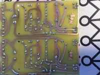
Use independent secondaries when feeding independent four diode bridges. If the burned PCB lane happened in the raw DC area it must be that scenario happened and also check if the CCS MOSFET connected to that route survived. Repair the lane with a jumper wire, replace any broken active or passive parts and it will be as new again.
To use a middle tap arranged transformer for two reg sections of opposite polarity you need classic single bridge and middle tap zero return raw DC arrangement that connects to all PCB zeroes. Like you commonly do with power amplifiers. Of course double bridges and independent secondaries offer raw DC return paths isolation.
To use a middle tap arranged transformer for two reg sections of opposite polarity you need classic single bridge and middle tap zero return raw DC arrangement that connects to all PCB zeroes. Like you commonly do with power amplifiers. Of course double bridges and independent secondaries offer raw DC return paths isolation.
Use independent secondaries when feeding independent four diode bridges. If the burned PCB lane happened in the raw DC area it must be that scenario happened and also check if the CCS MOSFET connected to that route survived. Repair the lane with a jumper wire, replace any broken active or passive parts and it will be as new again.
To use a middle tap arranged transformer for two reg sections of opposite polarity you need classic single bridge and middle tap zero return raw DC arrangement that connects to all PCB zeroes. Like you commonly do with power amplifiers. Of course double bridges and independent secondaries offer raw DC return paths isolation.
Hi and thanks for all support... great help Salas.
I have made an drawing where can be seen what i did yesterday when bigbang theory came to truth
Left top at picture, you see my pcb's. Right to that you can see how outputs was put together. (I guess this is correct)
On bottom left of picture, i have drawn in a "normal" transformer, which i normally use for all kind of stuff, including my Pass amp's.
The setup i had drawn on bottom right of picture, is the setup i tried yesterday, and there must be something wrong with that i suppose.
Reason i have serielconnected the transformer, is for getting 24VAC for the SSLV's... Both regulators have been tested with this setup, but without interconnection between them.
The 12vac outputs can feed my two ReflectorD's, which i also tested, and they also are working.
What do you suggest? -Using a 2x18vac transformer for the SSLV's, and keep the one 12vac transformer i got now for the reflectors?
Jesper.
Attachments
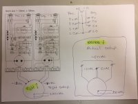
For 12V symmetric output CCSed shunt regs of double bridges use 15+15VAC dual secondary transformer in the way you have pictured at the bottom left corner of your attachment labeled "right". That will give near 20V rectified raw which brings enough dissipation across the CCS MOSFETs already (Watts = voltage drop input-output times the CCS current setting). 8V drop is more than enough for good working of the MOSFET CCS. Higher voltage transformers only create much more unwanted heat.
As for the outputs configuration forget for a while the sense lines (like when they are locally shorted to their force lines) and imagine two sections with +/0 and -/0 points only.
At the positive section the zero has negative potential to the plus. At the negative section the zero has positive potential to the minus. How would you connect two reservoir capacitors polarities across a symmetric raw DC supply? Naturally like +-+- and the middle -+ would be the common (zero) point. Same thing stands for the regulators outputs.
I also Think this what was happend when i connected the DAC earlier, then i thought that is was a shorted wire in a heatschrink tube...
Was it a CAT-5 like thin Kelvin wire? If yes it acted like a fuse and saved you the bang.
When you wired in three wire mode with thick cables later on... bang. The copper lane burned as an over-specified fuse this time allowing for more drama

For 12V symmetric output CCSed shunt regs of double bridges use 15+15VAC dual secondary transformer in the way you have pictured at the bottom left corner of your attachment labeled "right". That will give near 20V rectified raw which brings enough dissipation across the CCS MOSFETs already (Watts = voltage drop input-output times the CCS current setting). 8V drop is more than enough for good working of the MOSFET CCS. Higher voltage transformers only create much more unwanted heat.
As for the outputs configuration forget for a while the sense lines (like when they are locally shorted to their force lines) and imagine two sections with +/0 and -/0 points only.
At the positive section the zero has negative potential to the plus. At the negative section the zero has positive potential to the minus. How would you connect two reservoir capacitors polarities across a symmetric raw DC supply? Naturally like +-+- and the middle -+ would be the common (zero) point. Same thing stands for the regulators outputs.
Yes... this is where i come to short sometimes; i feel this potentiel part is difficult, but i know that it's ofcause right.
So even if i did use a "normal" say 2x15 transformer (like picture bottom left) and i connect like i have drawn at top right picture, the thing would have blown cause i connect the (+12vdc) -- (0) -- (0) -- (-12vdc), where it should have been connected (+12vdc) -- (0) -- (-12vdc) -- (0) ?
Jesper.
Was it a CAT-5 like thin Kelvin wire? If yes it acted like a fuse and saved you the bang.
When you wired in three wire mode with thick cables later on... bang. The copper lane burned as an over-specified fuse this time allowing for more drama
This was cross-posted
And it's right what you tell, it was some small non cat5 cables, and they blow, because it was the weakeast spot at that time
Jesper.
You connected the outputs well, I think the problem was the way you used the transformer
So the name Salas SSLV1.1 BIB -where BIB is short for ::
BiG Inrush BanG
Jesper.
Build dim bulb tester and have 40W 100W 250W bulbs for various power class experiments and servicing. It does mains current limiting. Glows bright with inrush then dims. If remaining bright says there's a short after it. If not a complete short, at least an over-current. At the same time it does not allow to the short all the current it can absorb. Burns in the bulb much as the filament gets hot and more resistive. Imagine a big over-current limiter PTC Thermistor that glows "WARNING" also.
a 40W 220Vac tungsten filament bulb passes ~182mAac when fully lit.
That implies a hot resistance of 1210ohms.
The fully cold resistance will be somewhere between 80ohms and 120ohms.
That cold resistance is the initial current limiter.
But the input voltage, the filament resistance and the load is an unstable system.
A kick in towards the overload condition brings the filament upto nearly full hot in a fraction of a second. The lower the bulb wattage the quicker this reaction.
When that happens the transformer primary sees a fraction of the mains voltage, usuall between 5% and 10% of mains voltage while the bulb is bright.
That brings down the secondary voltage to somewhere between 5% and 10% of it's rated voltage. Subtract 600 or 700mV for each diode in the bridge and there is very little voltage left to do any damage to any part of the faulty circuit/wiring.
For first power ON use a low wattage bulb. That does no harm. Try a 28W bulb if you have one on the shelf.
Last edited:
Who's the lucky boy?
I'am; My name is Jesper Lykke(Lucky) Petersen
Well Andrew, you seems to be knowing a hole lot of electronics, can you tell me what happend when i was powering them up with my 24vac trafo?
The interconnection between the two regulators was connected the right way, so it must be something when using single rail with two fullbridged psu?
Can you tell? Cause i cannot figure it out!
Jesper.
To blow the trace off, there must be a dead short that uses that area.
You can wire it up again and measure with a continuity meter (low ohms meter).
A Mains Bulb Tester fitted with a low wattage bulb would have saved this.
Hi Andrew...
I tried to wire it up, with an dual secundary transformer i have.
Everything is working now, and railvoltages are fully stable -12/0/+12.
Unfortunately i have no oscilloscope right now, but meassuring AC on rails shows practially zero mv.
So it is working as bipolar supply also with this setup. So something happening when using single rails transformer! So it must have something to do with missing transformer winding isolation between pos./neg. Regulator?
Jesper
- Home
- Amplifiers
- Power Supplies
- SSLV1.1 builds & fairy tales