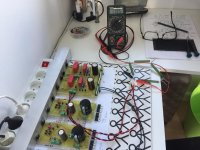
I made a sslv1.1 pcb to use with pearl phono. The board works with a dummy load and voltage can be adjust smoothly.
However when connect to the Pearl phono, there is a high pitched noise coming out with the music and it depends on volume. Voltage remains constant with the phono.
I then connect sslv 1.1 to headphone amp and the high pitched noise is gone.
What possibly cause this high pitch sound?
I'm using 10uf mkt for c102 c202. The phono has gain around 45-50db. Vin is 32vdc vout is 24vdc. Smoothing cap after the bridge is 6600uf for each rail. Current are set around 400-500ma.
I follow the component placement from the published Bibguiderev2.pdf.
Thank
Chatchai
so increase R1 to 30 Ohms should give me 400mA and decrease the temperature on Q106 heatsink?
Yes, try 400mA. About the exact R1 value considering your particular build tolerances you know best by the voltage drop you can measure across it
Hi.
I am going to try this shunt-regulator for my upcomming dac project")
Well, this dual-shunt will only be feeding the +12/-12 DC side of the dac; some reflectors will be feeding some other stuff at dac project
I am making those so to mount heatsink at end; mostly for them to share the heatsinks with other regulators...
Not all done with layout, but maybee somebody would comment the layout?
Jesper.
I am going to try this shunt-regulator for my upcomming dac project
Well, this dual-shunt will only be feeding the +12/-12 DC side of the dac; some reflectors will be feeding some other stuff at dac project
I am making those so to mount heatsink at end; mostly for them to share the heatsinks with other regulators...
Not all done with layout, but maybee somebody would comment the layout?
Jesper.
Attachments
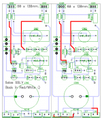
Simple layouts that follow the original for general view of parts positioning usually work when you double check that no connections are drawn wrong
Yes; will use some of the spare time next week, for checking schematics out for errors...
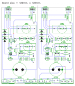
I cleaned the PCB a little up, making it single sided with only few top-jumpers.
Jesper.
Attachments
Evening all
I am lucky (As my middlename is), that both my +5/+3.3 ReflectorD's and the SSLV1.1 +12/-12 is working, eventhrough i did screwed a bit up along the build way through
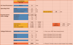
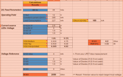
I have a quistion about the current adjustment for my SSLV, and that is, if it's possible to adjust the current source led's to to my current need, so that one of the three led will become a "highbright" 2.85v one, instead of the "EDITED GREEN one" 1.9v i use now, in let's say D102A/D202A...
Case is, that i need a bit more current for my dac-chip, and i don't have stock of R1's special 1watt's resistors (The one i use is 4,22ohm / 1W).
The spreadsheet, gives me the right numbers for this, but i am in doubt if it's right to do it this way?
I also must say, that i did have some problems understand the hole calculation part, but managed to understand most now i think...
Regards in advance from here!
Jesper.
I am lucky (As my middlename is
), that both my +5/+3.3 ReflectorD's and the SSLV1.1 +12/-12 is working, eventhrough i did screwed a bit up along the build way through I have a quistion about the current adjustment for my SSLV, and that is, if it's possible to adjust the current source led's to to my current need, so that one of the three led will become a "highbright" 2.85v one, instead of the "EDITED GREEN one" 1.9v i use now, in let's say D102A/D202A...
Case is, that i need a bit more current for my dac-chip, and i don't have stock of R1's special 1watt's resistors (The one i use is 4,22ohm / 1W).
The spreadsheet, gives me the right numbers for this, but i am in doubt if it's right to do it this way?
I also must say, that i did have some problems understand the hole calculation part, but managed to understand most now i think...
Regards in advance from here!
Jesper.
Attachments
Last edited:
Put highbright for now, but because its generally a noisier type of LED, replace with red again and with proper new R1 when able.
Input to the calc 2-3mA Vf not nominal Vf. That's usually stated for high mA like 20. See current/Vf curves of Leds in their datasheets.
Ahh... That's the deal
... Ofcause we don't want high noise parts here, but didn't expect my led's to make such nasty stuff through.Thanks Salas... You will be looking at the biggest PSU for a little DAC in the northern Europe
Jesper.
Ahh... That's the deal
Thanks Salas... You will be looking at the biggest PSU for a little DAC in the northern Europe
Jesper.
He he, no more just master psu but monster psu
If the DAC will be near, short sense+ with rail+ and sense- with rail- under the connectors and use three thick enough wires for conventional connection from rail+/0/rail- If you will bridge positive's return with negative's return you get a zero
For Kelvin see the pdf instructions
For Kelvin see the pdf instructions
If the DAC will be near, short sense+ with rail+ and sense- with rail- under the connectors and use three thick enough wires for conventional connection from rail+/0/rail- If you will bridge positive's return with negative's return you get a zero
For Kelvin see the pdf instructions
Okay... thanks
Jesper.
add a signal diode into the LED string..............I have a quistion about the current adjustment for my SSLV, and that is, if it's possible to adjust the current source led's to to my current need, so that one of the three led will become a "highbright" 2.85v one, instead of the "EDITED GREEN one" 1.9v i use now, in let's say D102A/D202A....................
That will increase the Vdrop by ~700mV
Okay... thanks
Jesper.
Imagine you do this and its analogous at the negative section:
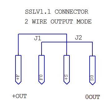
Now you got +OUT 0 OUT 0 OUT -OUT. Bridge 0+0 across sections. Three thick wires +/0/- you can output to the load.
If it was Kelvin mode you would bridge nothing and send F+ S+ to +Rail(Load) F0 S0 F0 S0 to 0 power ground (Load) F- S- to -Rail(Load). Each with a separate twisted pair. Thinner gauge than in conventional mode is permissible.
Thanks for clearing it out
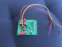
I think i will have to seperate DAC and PSU(s) in each seperate chassic; going for the kelvin mode with remote sensing through plugs i think.
Anyway i also think i will have to desolder the yellow one's (GND's), so that i can have two yellow on DAC left side, and two yellow on the DAC right side?
What do you think?
Jesper.
Attachments
Try both modes before fixing any connectors scheme because Kelvin can be very good for keeping low Zo across long distances but it also exposes the sense loop area to a possibly noisy environment. Try umbilical scale long Kelvin only with carefully made twisted pairs and/or coax. DACs usually care more about noise over Zo. Fix the best result mode in your case.
... okay then.I also have problems with fixing all those wires at the DAC, and had little accident to
.. Somehow (i think) two of them kelvin wires where shorted inside some heatschrinking i mounted after the picture was taking; ended up with "white" smoke from the wires; but looks as only wires was damaged.I tried the regulators afterwards, and they seems to be working allright still.
I cannot tell if DAC survied as i never tried it, and i have not been doing more work today
... hehe ... no more diy explosions today i guess...I will convert the two SSLV's to two-wire one's i think, and then try if DAC is working at all!
Happy easter, or what is left of it
Jesper.
Hi...
I guarantee that today is not my day

 !
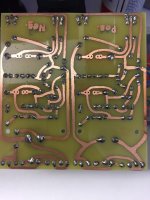
!I tried to connect the positive +12 and the negative -12 and their respectiable 0's into a 3 wire output.
I connected 50 ohm's load between (+12) --> (0) <-- (-12) and turned the thing on... phaaww! hmm... trace exploded with some nasty smoke...
I don't have a clue what is the case, but something must ofcause be wrong.
It will be a while until i will make new boards, but in meantime i perhaps will do an old-fashion LM7812/LM7912 regulator...
But hey
... One cannot win every time! right?Jesper.
Attachments
That usually means the Mains Bulb Tester is still on the shelf !
Hi...
I guarantee that today is not my day
I tried to connect the positive +12 and the negative -12 and their respectiable 0's into a 3 wire output.
I connected 50 ohm's load between (+12) --> (0) <-- (-12) and turned the thing on... phaaww! hmm... trace exploded with some nasty smoke...
- Home
- Amplifiers
- Power Supplies
- SSLV1.1 builds & fairy tales