Another bouncing baby Salas
Twins! A v1.2R pos and neg regulator!
I am totally addicted. I was listening to a very popular series regulator, but this is SO much better. I'm a huge floyd fan, and hearing things I've not heard before.
One question: I've read other posts where folks are using differing caps in their builds, but in many it's not explicitly called out. My guess is changing the big cap on the output, C2, would have the biggest impact on sonic character. Is there any practical benefit to be gained by experimenting with different values for C1 and C3 (the 4.7uF PPs)? Overall I'm extremely happy with the way it sounds, and I think I'm going to leave things exactly as they are. I'm just curious.
Hey, if no pictures it didn't happen.
Which series regulator? And remind us what you power? Is it a dac, a preamp?
Both the pp caps and electrolytic cap qualities have an impact, but slight in the greater scheme of things. The value and quality of the Vref filtering cap (C1) is rather more prominent.
Which series regulator? And remind us what you power? Is it a dac, a preamp?
Both the pp caps and electrolytic cap qualities have an impact, but slight in the greater scheme of things. The value and quality of the Vref filtering cap (C1) is rather more prominent.
Hey, if no pictures it didn't happen.
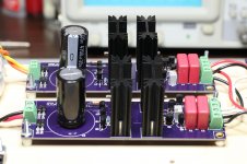
Birth certificate attached!
Color is classic OSH Park purple, but colors are off in the jpg... I mean certificate.Application is a headphone amp. Each amp is OPA2134/LME49600, straight from the TI datasheet. Each board draws +/-20mA quiescent, +/-40mA for the pair. Each regulator uses R1 = 5R6 for 107mA. Not using sense yet: boards support that by cutting trace on bottom. Cap C1 is WIMA MKS2 PP. Perhaps PPS might sound different, something to try. No 47uF on the output, each amp board has 470uF "bulk decoupling" cap on each rail, first thing. Maybe smaller caps on the amp board and 47uF on the regulator output. Something else to try.
The earlier series regulator is the Jung-Didden super-regulator found here:
https://linearaudio.nl/superregs
It served me well, and to my ears was a big improvement over a cap multiplier, but my ears like this sound a bit more.
Thanks for sharing the schematics. I'm very glad I tried this one.
Attachments
Looking nice, congrats. Kinda SSLV1.1 form factor looking. I hope that the on-board sinks suffice for your app. Depends on the cans you drive of course. Without 47u C2 you may have sense loop problems or not but two wire connection is no slouch either if kept short and thick. Better don't revise the reg/client app system when its a success. You used the K117s and BF256s subs we were talking about in the end? I can see a K117. I have recently promised to friends that I will revisit the 1.2R and make it more general use tamer and up to date accessible but no time found yet. It deserves it though.
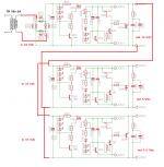
This is a pre-reg and two sub-regs scheme which is theoretically possible but I have not seen it done before with sslvs so to can foretell it will work flawlessly. If it will be oscillation free I mean. Use two wire connections between them and monitor the rails with the scope. One thing is that the master reg must have enough ccs current for the subs and little spare, another thing is to remember that all the sections must be same polarity. The "100" & "300" sections are positive, when the "200" board section is negative polarity.
Kinda SSLV1.1 form factor looking.
It does, doesn't it? Form follows function. I had no real plans for board size, I just started placing parts on a board, big pieces first, and, well... it happened.
I hope that the on-board sinks suffice for your app. Depends on the cans you drive of course
After 30 minutes of driving 25R headphones the heatsink for Q1 (current source) measures 37C. The heatsink for Q5 (shunt) measures 40C. Warm to touch, but not painful. Haven't measured with my 300R or 600R headphones yet, but don't expect any significant change.
You used the K117s and BF256s subs we were talking about in the end? I can see a K117
Yes, BF256 and K117 were relatively easy to obtain. Already had a bag of BC550/560. Now I have a few extra BF256 and K117 for next time.
I have recently promised to friends that I will revisit the 1.2R and make it more general use tamer and up to date accessible but no time found yet. It deserves it though.
I think it does. There was schematic capture error on the pos board, and layout (footprint) error on both boards, which is why I'm using smaller radial cap instead of larger snap-in. I'll be doing another turn in a week or two, and would be glad to try any changes you might have. But if it were me, it already sounds pretty good, I wouldn't change much.
Best regards,
Mike
PS - I'm in on the SSLV BIB group buy, will be interesting to compare those boards to these.
I don't revisit such delicate things hastily and I have other stuff on the bench now so don't expect changes anytime soon. Each version you see with a higher number has a greater performance potential. Just the 1.2R was not so widely compatible to be a generally recommended reg. But I will see about that with more available parts also in the near future.
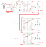
how about this one,
is it better like this?
thanks.
I think Salas meant that if the first reg gives lets say 600ma, then the 2 after it shouldn't go over about 250ma + 250ma. But if you cut off the CCS from the secondary regs, then even one of them will try to consume all the 600ma and no idea what the other one will do. Maybe as they try to fight each other for current they oscillate or smg like that. You should use the 2 secondary regs as before, just pay attention that they should never ask for more current then the first one can provide.
If this works then its nice let us know if it works.Hello,
can i use one transformer to supply everything i need
please take a look at picture, is it possible to do that
or any better idea if using only one transformer?
thanks.
You need a voltage dropping resistor, or similar, between the 15V output and the next shunt regulator.how about this one,
is it better like this?
thanks.
Otherwise the lowest voltage regulator (3.3V) drags the first reg's output down to 3.3V and severely overheats.
Are some of your transistors upside down?
Your choice of 18Vac to 24Vdc to 15Vdc seems practical.
15Vdc to 5Vdc should also work.
If your 3.3Vdc is high current, then the Pdiss going from 15Vdc to 3.3Vdc will be high.
You have to decide which side of your regulators use a Zero Volts reference and ensure that the outputs are all of the correct polarity.
Last edited:
Those represent two different preamp channels if I remember correctly? In that case mod the regs for two wire mode and branch out (Y) thick enough cables.
Yes, each channel has a separate + and - supply, sort of dual mono on a single PCB. Will do so then.
Every circuit is a flow and return route.
You must keep the flow and return route as a close coupled pair.
Single wires for interconnections between modules breaks that !
hello Andrew,
do you mean V.3 is the better one?
if yes, V.3 or V.4 better for chassis grounding?
thanks.
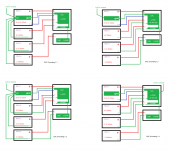
V1 and V2 both show single wire "AERIALS"
so must be discounted.
V3 and V4 seem to show close coupled Flow and Return. That is the only way to do it.
Consider what the CL60 is doing. Does it pass DC, or AC?
If any AC is passed, is it signal current or interference current?
Does it pass some AC only in some particular operating condition? or all the time?
When you know those answers you can decide what location least interferes with the wanted signal. I would be guessing because I don't know what your CL60 is supposed to do, too much is missing !
Last edited:
- Home
- Amplifiers
- Power Supplies
- SSLV1.1 builds & fairy tales