Just answered my own question! 3R3 just drops the voltage, doesn't solve the problem.
Short of rebuilding this I've run out of ideas, so I guess I'll quit now until I've tried some other supplies with the DAC. Your efforts in trying to solve the problem are greatly appreciated and if I do eventually get this working I'll post here.
Thanks again!
Short of rebuilding this I've run out of ideas, so I guess I'll quit now until I've tried some other supplies with the DAC. Your efforts in trying to solve the problem are greatly appreciated and if I do eventually get this working I'll post here.
Thanks again!
I think that RPi may peak demand beyond the recommended CCS limit for the Ref-D and clog up. Depends on how its configured. It takes to verify its happy with about 600mA CCS current limit. Or about 900mA with the SSLV. I.e. measure RPi max current demand on some brick PSU that it works well with it first by using a DMM in series amperage mode and the MAX-MIN function engaged.
A bit puzzled
I just completed and tested a positive and negative regulator from he latest boards and kits supplied by TeaBag. All has gone smoothly but I would like a better understanding of the results vs the calculated numbers.
I measured every LED, Jfet and Mosfet and plugged the chosen ones into the calculator. For 24V DC output at 110ma load and 200ma shunt the calculated value for R101 is 4R. Actual testing with a 200R dummy load produces 280ma across R101. Why the difference? Not much but curious.
Additionally, the calculated value of R105 is 5209R in my positive regulator but the actual measured value to obtain 24V after trimmer adjustment is 5960R. That's a big difference. Similar difference in the negative regulator. Why?
For this build what is considered a "hotrod" version?
Thanks for a well written build guide and for this hand holding.
nash
There are some necessary assumptions when feeding the calc regarding LEDS and their Vf at what test current. Those are connected to the various JFETs IDSS as they are driven from them in circuit. It becomes too detailed pre-testing to hit nearer predictions than ballpark. Also the Mosfets Vgs curve is textbook. They vary sample to sample from that curve in real life. But the calc's author had to pick a median reference curve. Best is you hit as near as practically predictable with basic testing and feeding the calc, then you adjust one or two resistors in the end. If proven non practically off ballpark that is. Hot-rod is considered in this neck of woods when you top the max current demand of the load with at least 200mA extra reserve in the CCS.
There are some necessary assumptions when feeding the calc regarding LEDS and their Vf at what test current. Those are connected to the various JFETs IDSS as they are driven from them in circuit. It becomes too detailed pre-testing to hit nearer predictions than ballpark. Also the Mosfets Vgs curve is textbook. They vary sample to sample from that curve in real life. But the calc's author had to pick a median reference curve. Best is you hit as near as practically predictable with basic testing and feeding the calc, then you adjust one or two resistors in the end. If proven non practically off ballpark that is. Hot-rod is considered in this neck of woods when you top the max current demand of the load with at least 200mA extra reserve in the CCS.
Thanks Salas. The slight difference between the actual and calculated current setting is probably because of the Mosfet Vgs difference between my measured and actual as you point out.
Regarding the difference in R105 between calculated and actual could it be perhaps because I used three green LED's instead of four and so the approx 33v DC drop to 24V DC had to be compensated by extra resistance from the trimmer?
Its related to to the Vref section components. Especially the Jfet that runs the red LEDs and trimmer. Say you have a confirmed Idss figure for it but when in circuit it will achieve less due to small voltage across it. 15-20% less depending on sample. Inevitably you compensate the rough prediction by more resistance in the trimmer. But that is what trimmers do ")
Its related to to the Vref section components. Especially the Jfet that runs the red LEDs and trimmer. Say you have a confirmed Idss figure for it but when in circuit it will achieve less due to small voltage across it. 15-20% less depending on sample. Inevitably you compensate the rough prediction by more resistance in the trimmer. But that is what trimmers do
OK. My Q103 Jfet works out at 14% less; in line with what you mention.
Since I am presently getting around 180ma shunt current with a 110ma load at 24V in each reg what would be the next worthwhile shunt current level to get an improvement in your opinion ? I am using a 24-0-24 50VA transformer for both the + and - regs and I think I have enough sink.
Thanks. nash
And such was about the extra resistance percent value you finally added in the trimmer setting, yes?OK. My Q103 Jfet works out at 14% less; in line with what you mention.
Since I am presently getting around 180ma shunt current with a 110ma load at 24V in each reg what would be the next worthwhile shunt current level to get an improvement in your opinion ? I am using a 24-0-24 50VA transformer for both the + and - regs and I think I have enough sink.
Thanks. nash
For example say you target a Class A preamp that draws 50mA steady bias. Before clipping its able to draw 100mA. So you would want to cover that and leave at least 50mA extra in the CCS setting for the reg's own needs and some margin. So 150mA CCS would suffice where 300mA CCS would be hot-rod enough (+200mA above absolutely necessary). And so on and so forth.
And such was about the extra resistance percent value you finally added in the trimmer setting, yes?
For example say you target a Class A preamp that draws 50mA steady bias. Before clipping its able to draw 100mA. So you would want to cover that and leave at least 50mA extra in the CCS setting for the reg's own needs and some margin. So 150mA CCS would suffice where 300mA CCS would be hot-rod enough (+200mA above absolutely necessary). And so on and so forth.
Yes. Measured 5209R and needed 5960R; so 14.4% extra was needed.
So for 110ma load, 420ma CCS would be the hot rod version. I guess a 50VA transformer would be pushing it ie 420x2=840ma? Right?
I don't think so because a cheap 50VA Antek AS-0524 for instance is rated for only 1V drop from nominal at 1.8A parallel draw or 41W from both secondaries as total. 2.1V drop rated at 2.7A 59W even. In your case (0.42X24)X2=20W.
The Antek AS-0524 is indeed what I have. I will keep it and buy R101's for around 420ma. If it gets too hot then I'll just step them down. No big deal.
Thanks again for your advice and explanations
nash
Thankyou Salas, I will use all 9530.
Would you also suggest brand and values for the other critical parts (such as capacitors and rectifiers...etc..etc) best for this application please??
Cheers,
King
Hi Salas,
Finally get some time to start on the sslv for my T amp project.
1) from the build guide, for 10V-25V, I should use 2 x 1.9V red LED.
2) should I use Zobel or Ecap output please?? (or which one should I try first??)
3) trying to learn to use the calculator, I plug in the followings:
DC in = 19V (I have a round power transformer of 18V-0V 4.4A + 18V-0V 4.4A); V out = 12V; Constant current = 2150 mA; Load current = 2000mA
With the above I got R103 + R105 = 3K
I do not know how to get R101 and P(R101), please help.
4) dummy load resistor for 12V @ 2A = 12/2 = 6R 50W
but how to simulate no load or very low load, from the T amp to study about the heat build up situation please??
***
Buy the way, I am still using your sslv to filament bias my 26 line amp....quiet as a pair of dead church mouse.
Cheers,
King
1. Yes
2. Zobel first
3. R101 on four green ccs leds depends on your powerful Mosfet type of choice also. For IRFP9240 at 2.15A CCS it could be 1.5R 15-20W resistor to hold well. It will burn 7W constantly on itself.
4. You know that for no load 2.15A * 12V is going to burn on the output Mosfet and you also know that for 2A peak draw only 0.15A * 12V will burn there. What goes to amp and speakers you remove from output Mosfet power burned on the reg. Thats the key for any power level dissipation to solve. But there is also the CCS to think about cooling which always burns 2.15A * (Vin-Vout).
Very inefficient and even dangerously hot way to power a T amp. But you already know that
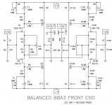
Output capacitors for BA3 FE with Salas BIIB supplies
Just completed building the two positive and two negative regulators and they all ran perfectly with dummy loads for over an hour. Bumped up the CC setting to 360ma for now. Will watch the heat and readjust when all is done.
I have not built a DCB1 but have read quite a bit of the thread and it appears that using symmetrical supplies has greatly reduced the need to use an output coupling capacitor and so there is none used, with usual caveats about a known good source, possible catastrophic regulator failure, etc. I am building a BA3 Balanced preamp using the BIIB regs. Do I really need the output cap shown as C3? Shouldn't the same thinking that went into not using the output cap in the DCB1 apply here?
Nash
Attachments
Although I have listened to one made by a friend and I had also run a simulation in a how much gain discussion over at its thread, I am not practically intimate with this design so to give you a definite answer. It is not having a CCS for its output stage and no relay to disengage fast so there should be DC drift until its output bias has settled and a power off DC cycle as the PSU capacitors will be drying out never exactly symmetrically. But better ask Nelson or expert builders. Someone may measure DC offset at the input side of the coupling capacitor for you.The supplies regulation type does not come into this BTW.
Although I have listened to one made by a friend and I had also run a simulation in a how much gain discussion over at its thread, I am not practically intimate with this design so to give you a definite answer. It is not having a CCS for its output stage and no relay to disengage fast so there should be DC drift until its output bias has settled and a power off DC cycle as the PSU capacitors will be drying out never exactly symmetrically. But better ask Nelson or expert builders. Someone may measure DC offset at the input side of the coupling capacitor for you.The supplies regulation type does not come into this BTW.
Thanks Salas. I participated in the gain discussion with you at that thread.
I think I will build it without C3 and R12 first and measure DC offset carefully for each phase and differentially and then decide. My fear is that not including C3 and R12 may lead to some weird oscillation?
Sans R12 there is some ground to think that and you should keep it, but the single coupling cap usually does not participate in stability. Because a series output resistor damps and gives more phase margin in the ultra HF open loop gain analysis of a loop feedback system. Where the capacitor is for blocking DC only and rarely comes into play for value and LF stability. Maybe you have heard about the "motorboating" LF oscillation effect in multistage tube amps, usually three stage ones with two couplings. I would not expect it here.Thanks Salas. I participated in the gain discussion with you at that thread.
I think I will build it without C3 and R12 first and measure DC offset carefully for each phase and differentially and then decide. My fear is that not including C3 and R12 may lead to some weird oscillation?
- Home
- Amplifiers
- Power Supplies
- SSLV1.1 builds & fairy tales