The bib pcbs are made as independent sections so the straightforward way is to use four wire secondaries (dual type transformer), each wires pair to each bib, and two bridges (available bridge diodes places are on each bib already) then unite at zero at the preamp's input. That's best.
I have a dual secondary transformer, so connecting at preamp input it is!!
")
Could I use the raw supply pcb of the phono simplistic to make a raw supply for the sslv in a separate case? It would make a nice psu case layout!
Last edited:
Considering this one channel.
Vin = {V Ground to Source} + {R101 Vdrop} = 25Vdc + 0.32Vdc = 25.32Vdc
Vout = 24Vdc
Vin-Vout = 1.32Vdrop
Am I reading the data correctly?
You're reading it correctly but I don't think I'm writing it correctly.
When I'm measuring across R101 I get 3.2Vdc. So that divided by 10R would give me .32A or 320ma. The .32A is what I've been writing down in my measurements.
The RAW FSP board only makes two positive polarity outputs. Its not a dual symmetric polarity board.I have a dual secondary transformer, so connecting at preamp input it is!!
Could I use the raw supply pcb of the phono simplistic to make a raw supply for the sslv in a separate case? It would make a nice psu case layout!
You're reading it correctly but I don't think I'm writing it correctly.
When I'm measuring across R101 I get 3.2Vdc. So that divided by 10R would give me .32A or 320ma. The .32A is what I've been writing down in my measurements.
You were writing those numbers without the A I think. Or it escaped our attention. "Vdrop" only hints Voltage. An "A" there would have alerted us.
When its in Ampere indeed your regs are fine and ready to go. We have solved the two other issues earlier i.e. one bad 9610 and one overshooting R13 value.
You were writing those numbers without the A I think. Or it escaped our attention. "Vdrop" only hints Voltage. An "A" there would have alerted us.
You're Kind. If I were at work and made a mistake like that my partner would have said "dumb ***".
Check across their R102 gate-stoppers. Is there voltage drop?
No voltage across R102
The RAW FSP board only makes two positive polarity outputs. Its not a dual symmetric polarity board.
Can't I just use it as a 2x single rail in the same pcb by turning one of the soothing capacitors 180º?
Last edited:
No voltage across R102
That is good. VGS develops across the two outer MOSFET pins without gate leakage. Maybe something goes wild when probing there at the gate and misleads. And I say so because having 7.45V LEDS drop and 2.8V-3.2V positive voltage drop across R101s. Since the VGS is subtracted from the LEDS VF it is weird for it to be really higher than the LEDS drop. You put the red probe on R101 to its left leg towards the reservoir capacitor and the black probe to its other leg for measuring its Vdrop and the DMM has shown positive voltage, right?
Can those MOSFETS be fake? Where you get them from? They looked rather OK in the photos.
You're Kind. If I were at work and made a mistake like that my partner would have said "dumb ***".
No worries. I do worse all the time.
Can't I just use it as a 2x single rail in the same pcb by turning one of the soothing capacitors 180º?
See the PSU schematic in the FSP guide. Its the same as in the RAW board. It only does not show the RD/LINK break between the bridges and the reservoirs.
If you think you can creatively fully reverse one section in that do so but I don't have the time right now to scrutinize and confirm. It would need to leave some components out that link grounds to lift circuits I would suppose.
That is good. VGS develops across the two outer MOSFET pins without gate leakage. Maybe something goes wild when probing there at the gate and misleads. And I say so because having 7.45V LEDS drop and 2.8V-3.2V positive voltage drop across R101s. Since the VGS is subtracted from the LEDS VF it is weird for it to be really higher than the LEDS drop. You put the red probe on R101 to its left leg towards the reservoir capacitor and the black probe to its other leg for measuring its Vdrop and the DMM has shown positive voltage, right?
Can those MOSFETS be fake? Where you get them from? They looked rather OK in the photos.
Yes, that's the way the probes where orientated. Mosfets were purchased from Mouser.
See the PSU schematic in the FSP guide. Its the same as in the RAW board. It only does not show the RD/LINK break between the bridges and the reservoirs.
If you think you can creatively fully reverse one section in that do so but I don't have the time right now to scrutinize and confirm. It would need to leave some components out that link grounds to lift circuits I would suppose.
Thinking about it why would I even change anything?
After the raw board I would have 2x 0-42V filtered. Won't it work if I just connect one of them out of phase with the other to the regulators?
Yes, that's the way the probes where orientated. Mosfets were purchased from Mouser.
Mouser is legit. When having healthy steady current indicated on R101 and R101 gets hot also, when the dummy load gets hot, when the Vout trims stably, then the whole reg works. About some weird indications I am not there to go hands on measuring and tell you for sure. I would try it for real.
Thinking about it why would I even change anything?
After the raw board I would have 2x 0-42V filtered. Won't it work if I just connect one of them out of phase with the other to the regulators?
I have only used two positive regs stacked floating as batteries using their common as centre so to make a virtual earth for their ends to appear +/-
General note
A four wire Kelvin output regulator does away with the cable voltage drop and the associated dynamic correction loop errors. But it also exposes the sense loop out in the interferences wild. The longer or the less well dressed and shielded the sense route the more danger due to wire inductance. Like a longer antenna. Or the sense nodes at the load maybe not working well if not best chosen. When not having an oscilloscope to confirm that the client preamp rails are interference free and oscillation free when on Kelvin mode, or to see if cleaner in conventional mode, then an indicative way is to subjectively compare it in conventional two wire mode also.
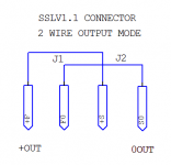
Four wire SSLV1.1 can be easily converted to conventional two wire with short jumpers in the output connector screws. For reliable permanent use, solder them under it. The jumpers should not touch between them. See attachment on how to put the BIB in conventional two wire mode* when interference is suspected by clues like noise / bad tonality / unexpected voltage drop, or just for the curiosity of comparing. Same jumper logic stands for the negative polarity output. When both modes are stable the Kelvin mode is superior. When two wire mode appears superior then there should have been some noise or instability on Kelvin mode. In conventional mode the two wires resistivity matters and they should be thick enough and not longer than necessary.
*To the contrary, conventional output regulators like most are, can not be readily converted to Kelvin (at least not without heavily hacking them or its impossible).
A four wire Kelvin output regulator does away with the cable voltage drop and the associated dynamic correction loop errors. But it also exposes the sense loop out in the interferences wild. The longer or the less well dressed and shielded the sense route the more danger due to wire inductance. Like a longer antenna. Or the sense nodes at the load maybe not working well if not best chosen. When not having an oscilloscope to confirm that the client preamp rails are interference free and oscillation free when on Kelvin mode, or to see if cleaner in conventional mode, then an indicative way is to subjectively compare it in conventional two wire mode also.
Four wire SSLV1.1 can be easily converted to conventional two wire with short jumpers in the output connector screws. For reliable permanent use, solder them under it. The jumpers should not touch between them. See attachment on how to put the BIB in conventional two wire mode* when interference is suspected by clues like noise / bad tonality / unexpected voltage drop, or just for the curiosity of comparing. Same jumper logic stands for the negative polarity output. When both modes are stable the Kelvin mode is superior. When two wire mode appears superior then there should have been some noise or instability on Kelvin mode. In conventional mode the two wires resistivity matters and they should be thick enough and not longer than necessary.
*To the contrary, conventional output regulators like most are, can not be readily converted to Kelvin (at least not without heavily hacking them or its impossible).
Attachments
I need to make a 12 wire umbilical between my psu case and preamp case.
4 wires raw DC for the simplistic phono.
4 wires for raw DC to feed 2 SSLV which will have around 250mA shunt current and raw voltage will be around ~41VDC.
4wires for relay attenuator/frontpanel dc and control.
Umbilical will be no longer than 1metre/3feet.
I found this one with 12 2x24wires: Mistral-2-4-8-12-16-20-24-32-48-Pair-Balanced-Multicore-Snake-Cable
2x24awg for each connection, is it enough for the SSLV and simplistic phono? Is a single 24awg wire enough?
The alternative is doing 3 cables with regular star quad but I would prefer a single cable in the back.
Last edited:
- Home
- Amplifiers
- Power Supplies
- SSLV1.1 builds & fairy tales