Hi Salas, yes thanks for the tip. The square wave is a little ordinary, I might experiment with this, it has 5 pico, I might try 10 and see what that does. I think it will easily handle lower gain, I am thinking 5 X gain instead of 10 X should be more than enough. Should I change the gain then tweak feedback capacitor?
First tweak the resistor, that will change the open loop gain phase margin as it will be exchanging gain for feedback. First check is to feed sine signal and see that the circuit does not oscillate. Then move to square. If still stable, tweak the cap in case the edges look pointy or ringing.
Hi Salas, I made the changes you suggested. Gain is now 5X and I installed a 50K pot. I didn't have a 10K, it seems fine. Im not sure this matters, I would think that a higher impedance is an easier load on the front end source, is that right?
I did the square wave and it looked OK as is, but I forgot to load it, so its probably not a valid test. I need to do it again tomorrow under load. I use a website to generate the wave as I don't have a signal generator. Its probably time to get one.
The power supply is so clean, I cant even measure the ripple on this, maybe less than a mV when playing.
interesting thing with my headphones, I prefer the old HP1000, they don't have the bass and presence of the Fidelio L1, but the separation between instruments is better, clarity, it doesn't sound exaggerated, its more natural. I still like my F4, its a very laid back amp.
I think I need to get to work on the next project soon. I have a Saphire Mk3 to get going soon. Maybe I shouldn't be so cheap and buy a proper case for it")
Thanks again for your help, Teabag too for the boards if your out there.
I did the square wave and it looked OK as is, but I forgot to load it, so its probably not a valid test. I need to do it again tomorrow under load. I use a website to generate the wave as I don't have a signal generator. Its probably time to get one.
The power supply is so clean, I cant even measure the ripple on this, maybe less than a mV when playing.
interesting thing with my headphones, I prefer the old HP1000, they don't have the bass and presence of the Fidelio L1, but the separation between instruments is better, clarity, it doesn't sound exaggerated, its more natural. I still like my F4, its a very laid back amp.
I think I need to get to work on the next project soon. I have a Saphire Mk3 to get going soon. Maybe I shouldn't be so cheap and buy a proper case for it
Thanks again for your help, Teabag too for the boards if your out there.
50K is easier on sources. That Dynalo circuit has high parasitic capacitance JFETs but a feedback loop too that should keep the bandwidth wide enough with 50K also. If you had a wide band generator you could check its -3dB high frequency limit.
From my PC running a tone generator website with 44.1kHz sampled tones for a quick test to a 200MHZ scope, I did not get a smooth 1kHz square. The few harmonics available for constructing it due to narrow 20kHz bandwidth were too apparent. 10kHz square was already a sine wave. Even at 100Hz or bellow where it could iron out due to enough components, the edges were still ringing due to the brick filtering. Before reaching 0.5Vpp the noise was bad too. Thus I am not sure you can compensate a feedback loop reliably with such a PC gen. I am attaching a screenshot.
Apply a 33pF across the series feedback resistor for now and check if it mellows out by ear. When having some savings I recommend GW Instek SFG-1013 as a minimal & affordable reliable gen from a reputable enough manufacturer.
As for the shunt PSU you found it clean and stable, the scope alone is enough and no further work in that department is needed for you to do. Congrats.
Attachments
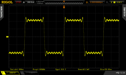
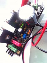
That picture is what mine looks like, maybe same generator If you accept the ringing is part of the generator, then at least the wave is square rather than saw. For now I have a friend who is overseas on business for three weeks. He has very good equipment so I may go there and get it right. I still need to output to RCA and try it as a preamp, but I need more cable. There is also some cosmetic work, but all in all its a very nice amp, quite neutral and natural sound, not colored and romantic like say the M3 which didn't appeal.
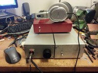
Last pic with the ferrari red TP Opus dac and the not so attractive but very nice sounding philips cans.
If you accept the ringing is part of the generator, then at least the wave is square rather than saw. For now I have a friend who is overseas on business for three weeks. He has very good equipment so I may go there and get it right. I still need to output to RCA and try it as a preamp, but I need more cable. There is also some cosmetic work, but all in all its a very nice amp, quite neutral and natural sound, not colored and romantic like say the M3 which didn't appeal.Last pic with the ferrari red TP Opus dac and the not so attractive but very nice sounding philips cans.
Hi Salas,
I need to modify a positive Mosfet BiB for higher current to supply a Buffalo DAC at 5V3.
With the older local shunt regs, load current was about 450-500mA and with R101=1R1 and voltage across R101 about 0.88V, BiB current setting was 0.8A.
Now i changed the local regs and my new load current is about 0.76A, so i have no spare shunt current and I' m experiencing a 0.35V sag after a few minutes, so i need to increase current setting.
Is it safe to further decrease R101 value, or should I add one more led?
BiB shunt regulators stuck at 3.3V
Hi all
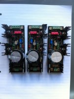
I have built 3 salas back in black shunt regulators today to power the analog elements of my TPA Opus DAC and IVY I/V. The power supplies are designed for +15V, -15V, and +7.5V.
I have used 22 ohm current source resistors, and 10,000uf main filter caps (overkill I know).
However I have an issue. When I test them (with a 20ohm / 5w dummy load) all of them are stuck at 3V on the output.
The output does not change no matter how much I rotate the trimmer up or down.
I should mention the green leds light up okay, the red ones barely light up.
I am clearly doing something wrong with all of them not working, has anybody encountered this before?
Hi all
I have built 3 salas back in black shunt regulators today to power the analog elements of my TPA Opus DAC and IVY I/V. The power supplies are designed for +15V, -15V, and +7.5V.
I have used 22 ohm current source resistors, and 10,000uf main filter caps (overkill I know).
However I have an issue. When I test them (with a 20ohm / 5w dummy load) all of them are stuck at 3V on the output.
The output does not change no matter how much I rotate the trimmer up or down.
I should mention the green leds light up okay, the red ones barely light up.
I am clearly doing something wrong with all of them not working, has anybody encountered this before?
Attachments
Sorry I don't understand your calculation, where do you get this 0.6V value?
I basically followed this procedure from Salas's guide:
*By reading the ID/VGS curve you can have an idea of VGS at your projected CCS current.
The curve differs enough in production, it is silicon wafer process related. This one is for the IRF9610.
At current of 0.5A, it reads about 5.1V for instance. That value has to be subtracted from what forward
drop is available by the LEDS array. What remains is the voltage across R101(201,301). By dividing
that drop with R101 value in Ohm, the CCS current setting is found. In the newer batch of SSLV1.1
boards, 4 LED positions are available for ease in higher current settings. They can either be used for 3
LEDS and one of them be a wire jumper, or be fully populated if your current demands push VGS and
your resistors stock fits higher values. Excess voltage across R101 when there is enough to set the
CCS with fewer LEDS, only creates excess dissipation, gives no advantages. A ballpark example would
be 15 Ohm and 4 green LEDS or 4.7 Ohm and 3 green LEDS for circa 200mA CCS.
I want each power supply to provide a bit less than 200ma.
Is the problem my CCS resistor value? Should I have gone for a smaller value?
I just checked again and my calculation seems to be off.
For 200ma the chart reads 4.7V. The led string is 4x 1.8V = 7.2V.
(7.2-4.7)/0.2=12.5 ohm
So there you go i think the problem is with my 22ohm it's very close to switching the mosfet off.
I think i will parallel another 22 ohm for a 11 ohms total on the CCS.
For 200ma the chart reads 4.7V. The led string is 4x 1.8V = 7.2V.
(7.2-4.7)/0.2=12.5 ohm
So there you go i think the problem is with my 22ohm it's very close to switching the mosfet off.
I think i will parallel another 22 ohm for a 11 ohms total on the CCS.

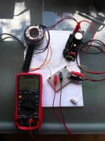
Success! I paralleled a few resistors to get 10R CCS and used 220R as load. Everything works as it should now! Thanks Salas  !!
!!
NB: 14.900V just to demonstrate accuracy to 3 decimal places !
!!NB: 14.900V just to demonstrate accuracy to 3 decimal places !
Attachments
Last edited:
Very nice. Make sure you will have enough ventilation since the sinks are not that big.Success! I paralleled a few resistors to get 10R CCS and used 220R as load. Everything works as it should now! Thanks Salas
NB: 14.900V just to demonstrate accuracy to 3 decimal places !
- Home
- Amplifiers
- Power Supplies
- SSLV1.1 builds & fairy tales