Nowhere, its normal. Nominal Vf is at nominal 20mA when those circuit positions run few mA. Just plug what actual numbers you measure in the xls.
Ive tested it with dummy loads with 36R.
By tweaking the trimmer SSLV only gets as high as 9.9V instead of 12V.
Is this because I had CCS too high for about 400ma with 100ma load consumption?
Last edited:
P.S. For what you ask in the top edit, you probably got less CCS setting than you might think. Measure that across R101 (&201) as voltage and divide by its Ohmic value to derive current. Use a lighter dummy (more Ohm) bcs now you overload it for sure. If you want to simulate 100mA load at 12V, use 120R and so on and so forth.
Examine the current setting resistors. Do they look discolored? Do they measure nominal Ohms? Can you measure a small steady voltage on them when power is on?
When all LEDS are on, current setting resistors pass the above checks, output voltage responds to trimmer and can stay steady, then your regs survived.
When all LEDS are on, current setting resistors pass the above checks, output voltage responds to trimmer and can stay steady, then your regs survived.
P.S. For what you ask in the top edit, you probably got less CCS setting than you might think. Measure that across R101 (&201) as voltage and divide by its Ohmic value to derive current. Use a lighter dummy (more Ohm) bcs now you overload it for sure. If you want to simulate 100mA load at 12V, use 120R and so on and so forth.
I ended up to use much high value on R105 to get to 12V (about 800R higher than calculated value 2050). Tested on 200R and 40R load.
And Im getting 3v across 10R on CCS, so yes I got less than my overkill design, yet still enough.
Last edited:
Examine the current setting resistors. Do they look discolored? Do they measure nominal Ohms? Can you measure a small steady voltage on them when power is on?
When all LEDS are on, current setting resistors pass the above checks, output voltage responds to trimmer and can stay steady, then your regs survived.
Yes, current setting resistor input leg started to decolour but the resistor was high enough in the air so the poison didn't reach the body
") Yes, it reads ok, there's a steady voltage on it, all is steady. Reg survived. Anyway, I will change a resistor to a new one. I was scared the mosfets should be changed - it's hard to find those in Russia. Thank you, Salas!
Yes, it reads ok, there's a steady voltage on it, all is steady. Reg survived. Anyway, I will change a resistor to a new one. I was scared the mosfets should be changed - it's hard to find those in Russia. Thank you, Salas! супер
суперIf the idss of the fet in the Vref is bit low then its normal to need more resistance. Did you measure its idss first and it proved different than the calculation, or it was one you put there by chance?
I guess my mA meter is bit off, so I put down some 3mA ones instead of 4mA.
Don't use a mA ammeter.
Use a 1% resistor and a 0.5% voltmeter.
Then your worst error is ~ 1.5%
Thanks for the advise.
Now im in a new pit.
Everything seems working until it is plugged in with my headphone amp.
no smoke and music is playing, except the bass is broken.
The led on the amp dims periodically-ish and thats when the bass breaks.
Last edited:
Thanks for the advise.
Now im in a new pit.
Everything seems working until it is plugged in with my headphone amp.
no smoke and music is playing, except the bass is broken.
The led on the amp dims periodically-ish and thats when the bass breaks.
LED dims even the amp is idle, i put voltage meters on the output of sslv no voltage change is observed during that by my bare eyes.
By using Ameter in series with the older supply and the amp's receiving points confirm the mA consumption of the amp to make sure its not limited by your CCS setting. Confirm your CCS allowance by measuring voltage across R101-201, solving for CCS(mA)=VRset/Rset. If in no doubt already, firstly check that the 4 wire connections are done correctly to the amp's proper receiving nodes. Or change for other receiving nodes, or shorten the cables, or remove some possibly installed small value decoupling capacitors across those nodes in case your amp goes to some oscillation when cooperating with the new regulators. Those are wide bandwidth designs and maybe something in the headphones amp acts up. Oscilloscope is the tool to observe such things.
By using Ameter in series with the older supply and the amp's receiving points confirm the mA consumption of the amp to make sure its not limited by your CCS setting. Confirm your CCS allowance by measuring voltage across R101-201, solving for CCS(mA)=VRset/Rset. If in no doubt already, firstly check that the 4 wire connections are done correctly to the amp's proper receiving nodes. Or change for other receiving nodes, or shorten the cables, or remove some possibly installed small value decoupling capacitors across those nodes in case your amp goes to some oscillation when cooperating with the new regulators. Those are wide bandwidth designs and maybe something in the headphones amp acts up. Oscilloscope is the tool to observe such things.
wire connection is good, a ethernet cable (4 twisted pairs) is used, and the 4 ground wires merge at the amp.
CCS draws around 300ma (3v over 10R) as planned.
I think the problem lies on the dc servo on the amp side.
the servo reacts too slow somehow causes the drop. I have no idea why this isn't happening with previous off the shelf ps.
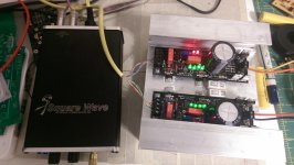
Post a close clear photo of the headphones amp with the regs connected.
the amp is a sp singlepower modified according to gilmores dc servo design.
running on +-12v rails and using original design to control bias, everything else implemented as the pdf.
http://gilmore.chem.northwestern.edu/squarewaveproduction.pdf
Attachments
Last edited:
- Home
- Amplifiers
- Power Supplies
- SSLV1.1 builds & fairy tales