The output voltage of a choke input filter is ~ 0.9*Vac
The output of a capacitor input filter is ~ 1.4* Vac
BUT !!!!!! the choke input filter requires a narrow range of load current to give the predicted output voltage.
When the load current drops below the required value, the output voltage rises towards the capacitor input voltage., i.e. the output voltage rises by ~50% at very low currents.
He has a bleeder but now he is going clc anyway. Choke input could do with snubbing too for compensating the ringing when the bridge diodes cut off.
CLC did not help. Nose is got up.
However, I did not used two identical Cs.
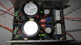
I used what I have: out from rectifier -> 4700uF 63V Nichicon KG -> choke -> 1000uF 50V Elna RSF.
Snubbing on choke or on rectifier diodes?
Set for when hot. Change one LED for a common silicon diode if still sliding on the positive. Depends on thermals in some builds and on transistor samples. Also on trimmer and resistor ppm.
Solved by replace with a new BC550
") .
.Thank you .
uhm..uhm, This error has not been resolved. I do not know why?, before that I had run over 1 hour for test, the voltage DC drop and last measured is 14.75 -14.76 vdc.
Now, start point at 14.44VDC and increased 0.5VDC after >30 minutes. Should I note the red zoned in the image ? . I will check carefully and let you know .
Thanks you .
Now, start point at 14.44VDC and increased 0.5VDC after >30 minutes. Should I note the red zoned in the image ? . I will check carefully and let you know .
Thanks you .
Attachments
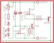
What value R103 & R105 you use?
I used R103= 1300 Ohm , R105 = Trimer 5K Ohm .
Use best part of total towards the fixed resistor to reduce the contribution of the trimmer only to what is needed to adjust over a small comfortable range. The trimmer is more unstable than an good ppm fixed resistor especially with hot sinks so near. Measure now across trimmer and resistor to know the total you use in ohm so to proportion better. With power off.
I would avoid. Especially at that distance.
I see. I'm not going to use.
Thank you.
Did you try the diode instead of one led of the red pair or just jumper I firstly suggested?
Sorry, I think that has solved so not try. For clarity, I should replace one red Led by diode ( N4001,N4007) ? . I will try soon .
- Home
- Amplifiers
- Power Supplies
- SSLV1.1 builds & fairy tales