One question, i have test-run my SSLV1.1's and my vdrop over the pre-reg parts (choke small choke also) was a bit bigger than i first thought, and the transformer had a little bit less output than i thought (16.5vac instead of 17vac) But anyway:
I will only use this shunt for ~115-120mA total current, and wanted to have 17.5V output. And i have ~19.5v before the current-set resistor and the IRF9610. Using 10R current-set dropping approx 1.18v over that resistor. Leaving only ~0.8-0.9v Drain-Source over the IRF9610.
I will use this to feed the SEN i/v, and when i measure on the V-input of the SEN i do actually have 17.45V and no ripple (with the multimeter at least). I don't have all parts so that i can test it together with the DAC, but i will do so later..
So my question is - will this be any trouble running so low Drain-Source over the IRF9610? looking at datasheet i think it should be possible, but i'm not best at understanding all data.. so any thought about this?
Low VDS makes the MOSFET more capacitive as a CCS worsening it in HF, and the whole reg susceptible to pass ripple in case the mains drop more at a point.
The CCS becomes limp for significant current changes on the output side also.
Bottom line is do something to up your input voltage. Lose the input filter if you can't use another transformer for now. Use 1 Ohm/1W in its place just to break EMI byproducts from the charge cycle.
The CCS becomes limp for significant current changes on the output side also.
Bottom line is do something to up your input voltage. Lose the input filter if you can't use another transformer for now. Use 1 Ohm/1W in its place just to break EMI byproducts from the charge cycle.
Strange thing is that i measure 16.5VAC before rectifier, then after that 1500uF Cap -> common mode choke 2x100mH/3R -> 1500uF cap. And if i measure after my rectifier i only have ~20.2V even though my diodes are low-dropout schottky SMD's. then dropping approx 0.7V over then chokes.. So the LC filter doesn't seem to drop to much, but i rather have to low voltage after the rectifier and cannot figure out why.
Hello there 
Just asked some quistions in the other salas shunt thread, which i see, could be hard to understand!
So, i ask straight out instead :
I need 700mA (Raspberry PI) + 25% ~950mA current.
I have a 12vac transformator
Would like to use the excellent shunt for 5vdc feeding the PI.
-Anyone help, with the desired values ?
/Jesper.
Hmmm.
I generally do not think the Salas is the best choice for running a computer like this, here's why:
A computer board is going to have widely varying current needs, the listed value of 700 mA at 5V is probably a maximum which the board will draw at boot up, and when working really hard (processor maxed out), the problem is, if you are using it to play music, the processor will probably run at around 5%, and the board will probably draw much less current, perhaps half (350 mA). If you set the CCS on the Salas for 1A to accommodate the max current needed, you will have to have some huge heatsinks to get rid of the other 650 mA at 5V of heat (3.25 watts), plus, you are making the situation even more difficult by having a 12V transformer, as now you also have to handle around 11 volts of drop to reach your 5 volt output. You could make this work, but you will need really, really impressive heatsinking. At least get yourself an 8 volt transformer to make it a little easier...
The Salas is really better suited to loads which do not vary quite so much as a computer board.
I would try around 2 ohms as a start for the CCS resistor, and usually around 220R and two red leds will get five volts. Typically you will have to experiment a bit with these values to get exactly what you need. Note that you will likely have to meet the maximum current demands of the Rasberry Pi for it to boot up, otherwise the output voltage will drop. Make to sure to test everything with a good dummy load: a 7 ohm 10W resistor would give about 715 mA draw at 5 volts output.
Hello there
Just asked some quistions in the other salas shunt thread, which i see, could be hard to understand!
So, i ask straight out instead :
I need 700mA (Raspberry PI) + 25% ~950mA current.
I have a 12vac transformator
Would like to use the excellent shunt for 5vdc feeding the PI.
-Anyone help, with the desired values ?
/Jesper.
I generally do not think the Salas is the best choice for running a computer like this, here's why:
A computer board is going to have widely varying current needs, the listed value of 700 mA at 5V is probably a maximum which the board will draw at boot up, and when working really hard (processor maxed out), the problem is, if you are using it to play music, the processor will probably run at around 5%, and the board will probably draw much less current, perhaps half (350 mA). If you set the CCS on the Salas for 1A to accommodate the max current needed, you will have to have some huge heatsinks to get rid of the other 650 mA at 5V of heat (3.25 watts), plus, you are making the situation even more difficult by having a 12V transformer, as now you also have to handle around 11 volts of drop to reach your 5 volt output. You could make this work, but you will need really, really impressive heatsinking. At least get yourself an 8 volt transformer to make it a little easier...
The Salas is really better suited to loads which do not vary quite so much as a computer board.
I would try around 2 ohms as a start for the CCS resistor, and usually around 220R and two red leds will get five volts. Typically you will have to experiment a bit with these values to get exactly what you need. Note that you will likely have to meet the maximum current demands of the Rasberry Pi for it to boot up, otherwise the output voltage will drop. Make to sure to test everything with a good dummy load: a 7 ohm 10W resistor would give about 715 mA draw at 5 volts output.
Mr. Salas, you make one tough regulator. I finally finished putting my BiB and OpenAmp1 phono preamp into their very-tight enclosure, and wiring everything up. I plugged in the umbilical from the raw DC supply and heard a faint *pop*. The negative regulator was fine, but the positive had basically no output voltage, and the red LED's (D105/106) were not lit. I assumed I had blown something up, although I saw no smoke and nothing smelled burned. This was very frustrating since the assembled regulator boards had been tested outside the enclosure, so I knew the boards were assembled properly.
Tonight after staring at the schematic a while I powered it up again and started measuring. I could't make sense of it, except Q101 didn't seem to be conducting although there was some voltage drop across R101. I finally double checked the wiring between the 2 boards, and sure enough I had swapped the +/0 from the positive regulator to the preamp! So I was running that regulator with a shorted output. I got the wires swapped (no small task since there is basically NO clearance and I didn't want to disassemble everything) and tried it, it flashed right up, all LED's on, +15V output as expected!
Still need to do some testing of the preamp before I can listen, but I want to say "Thanks!" for making such a robust regulator. My little mistake would have fried many voltage regulators.
I will post some photos of the complete build in a day or two.
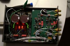
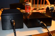
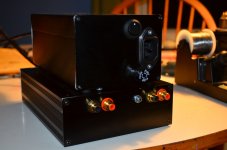
Here are some pics of my completed OpenAmp1 phono preamp with Salas BiB regulators. I put the raw DC supply in a separate chassis. The raw supply consists of a filtered 6A power inlet, fuse holder, and power switch feeding a Triad 56VA 36V center-tapped transformer. The xformer output is rectified by a bridge made from 4 MUR820's. Each rail goes through a 0R2 wirewound to an 80V 4700uF cap, then a 10R wirewound to a second 4700uF, thence to an XLR socket. The output from the center tap is connected to the chassis via 2 diodes, and to the filter caps and on to the XLR via a heavy piece of solid copper wire.
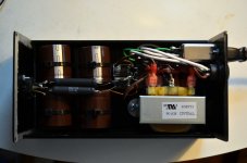
Here is the actual amp chassis, all LED's glowing!
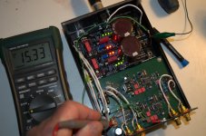
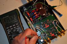
Verifying voltages:
Here are external shots when they are all zipped up.
I'll test the amp board for offset tomorrow, then hopefully listen to it!

Here is the actual amp chassis, all LED's glowing!

Verifying voltages:


Here are external shots when they are all zipped up.


I'll test the amp board for offset tomorrow, then hopefully listen to it!
Last edited:
Since you asked: Today I powered it up again and measured the output offset voltage of the preamp (which has a servo circuit), it was 0.0mV in both channels with shorted inputs. So I hooked it up to my TT (Thorens TD160 with original TP16 tonearm and Signet TK-7e cart) and to my DCB1. It sounded great! Before playing music I turned up the volume on the DCB1, no noise or hum. Then played a record (Toshiko Akiyoshi/Lew Tabackin "Tales of a Courtesan") and it sounded fantastic. Almost too good in the bass, I need to make some adjustments to the old Thorens I think, it seems more sensitive to footfalls than before. Great definition etc etc (all the good things we say about amplifiers). I don't know how much is due to PMA's phono board, or how much to the BiB, but they make a great combination. Oh, the BiB is running pretty warm, too, the case heats up noticeably (280mA per rail, and I doubt the phono board consumes 100mA).
Last edited:
Not that I am aware, you could check with PMA (member here).
Preamplifier for MM cartridge
Preamplifier for MM cartridge
No, my speakers are very smallish! However, they are "honest 50Hz" but can produce significant output down to 30Hz if you can live with some distortion. The 5.25-inch woofers have pretty dramatic excursion on LF events like record warps and footfalls.
PLUTO-2.1 omni-directional loudspeaker
review of older v2: http://theaudiocritic.com/plog/index.php?op=ViewArticle&articleId=37&blogId=1
Yes, turntable support, and arm-cartridge resonance, and suspension tuning, are all areas where I need a little fine-tuning.
PLUTO-2.1 omni-directional loudspeaker
review of older v2: http://theaudiocritic.com/plog/index.php?op=ViewArticle&articleId=37&blogId=1
Yes, turntable support, and arm-cartridge resonance, and suspension tuning, are all areas where I need a little fine-tuning.
No, my speakers are very smallish! However, they are "honest 50Hz" but can produce significant output down to 30Hz if you can live with some distortion. The 5.25-inch woofers have pretty dramatic excursion on LF events like record warps and footfalls.
PLUTO-2.1 omni-directional loudspeaker
review of older v2: http://theaudiocritic.com/plog/index.php?op=ViewArticle&articleId=37&blogId=1
Yes, turntable support, and arm-cartridge resonance, and suspension tuning, are all areas where I need a little fine-tuning.
Maybe an extra subsonic passive in the active speaker's LF amp if other measures won't prove efficient.
- Home
- Amplifiers
- Power Supplies
- SSLV1.1 builds & fairy tales