Hey everyone,
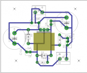
I'm trying to put together my first Eagle PCB project, a LM317 regulator for my newly built NP-100v12 12AU7 headphone amp. It takes 15v from a wall SMPS and brings it down to 12.5v for the amp. I'm using a portion of the Millett Hybrid Max, per this comment on the NP-100v12 support thread.
Can anyone suggest changes or point out errors? I honestly am amazed I have gotten this far. I'll be printing this and doing an iron transfer to etch a single sided board. Thanks!
Attachments
Hi Tommy_O, the main concern I would have is that the input to output voltage may not be high enough. If your 15V smps is providing higher than 15V (ideally 17.5V or a bit higher) then you should be fine. 2.5V I think will result in less than optimal performance.
I'll let some others comment on the layout. I'm not keen on it, but I'm no expert") I'd be trying to get the reg close to the output and would definitely get your resistors as close to the reg as possible. The datasheet has some tips on this.
I'd be trying to get the reg close to the output and would definitely get your resistors as close to the reg as possible. The datasheet has some tips on this.
Tony.
I'll let some others comment on the layout. I'm not keen on it, but I'm no expert
I'd be trying to get the reg close to the output and would definitely get your resistors as close to the reg as possible. The datasheet has some tips on this. Tony.
Hi Tommy_O, the main concern I would have is that the input to output voltage may not be high enough. If your 15V smps is providing higher than 15V (ideally 17.5V or a bit higher) then you should be fine. 2.5V I think will result in less than optimal performance.
I'll let some others comment on the layout. I'm not keen on it, but I'm no expert
Tony.
I will keep in mind the voltage difference for the power supply. I have several on hand from 24v to 15v and will test them to find the most suitable solution.
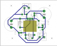
I can't seem to find the relevant information in the datasheet for the LM317 on the distance of resistors. However, after reading your comment, I did notice that R2 could be flipped and the routes would work better. Unfortunately, the only heatsink I have came from Radioshack and doesn't allow me to move parts closer to the regulator. If this is a problem I'll source one from Digikey.
Attachments
A quick search shows that headamp draws 400mA, is this correct because I based further comment on that assumption (or near that value at least)?
Based on the genuine national semicon LM317 (that datasheet), and let's assume a modest thermal rise over ambient to 50C operating temp (if it gets hotter which is reasonably likely the following number is even smaller), at 400mA output the forward drop of LM317 is roughly 1.7V, it should not have a problem regulating to 12.5V from 15V input for your use. While aiming for at least 3V forward drop is the safe/conservative answer, in practice you should have no problem with 2.5V forward drop at 400mA current.
Now having written that, you do not need 2 x 1000uF capacitance when this circuit is following a regulated switching power supply, that would be more useful if it were following an unregulated transformer but after a SMPS operating in tens of KHz frequency region, a 20uF tantalum and 1uF film or ceramic is all you need,
Make wider traces, there is no use to make them as thin as possible. Once you've removed the excess capacitance you can put the resistors closer, BUT it won't make much difference how far your resistors are away if you use a bit thicker traces and maybe even without doing that. The next improvement over what you have would be if you had a ground plane for reduced noise pickup.
With 400mA current, and (15V-12.5V) 2.5V drop, you're dissipating 1W. The heatsink area you have allotted should handle 1W fine but going much higher in input voltage than 15V, the heatsink will soon be inadequately sized for most enclosure situations... although I can only assume it is a typical height, if it's really tall heatsink then it "could" still have sufficient surface area to dissipate more heat.
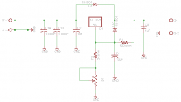
Variable resistor R3 is not needed if it is not important to be able to dial in 12.500000 V exactly, it could be 12.4V, 12.5343353V, etc, so long as it is a steady/clean output. Humans like nice round numbers but electronic components don't care so much. I am suggesting to just calculate the two fixed resistor values you need for the target output voltage and that will be fine AND you won't have to worry about contact degradation drift that mechanical pots/etc suffer over time.
Although above I wrote that you don't need this much capacitance, implying it means you can use the available area better, there could still be usefulness in this design because you can reuse the design for when you do want to power a regulator board with just a transformer and diode bridge instead of a regulated SMPS in front of it, not having to redesign it all over again.
Putting the regulator close(r) to the output won't do much when you have an output that then connects via wire to something else anyway.
Based on the genuine national semicon LM317 (that datasheet), and let's assume a modest thermal rise over ambient to 50C operating temp (if it gets hotter which is reasonably likely the following number is even smaller), at 400mA output the forward drop of LM317 is roughly 1.7V, it should not have a problem regulating to 12.5V from 15V input for your use. While aiming for at least 3V forward drop is the safe/conservative answer, in practice you should have no problem with 2.5V forward drop at 400mA current.
Now having written that, you do not need 2 x 1000uF capacitance when this circuit is following a regulated switching power supply, that would be more useful if it were following an unregulated transformer but after a SMPS operating in tens of KHz frequency region, a 20uF tantalum and 1uF film or ceramic is all you need,
Make wider traces, there is no use to make them as thin as possible. Once you've removed the excess capacitance you can put the resistors closer, BUT it won't make much difference how far your resistors are away if you use a bit thicker traces and maybe even without doing that. The next improvement over what you have would be if you had a ground plane for reduced noise pickup.
With 400mA current, and (15V-12.5V) 2.5V drop, you're dissipating 1W. The heatsink area you have allotted should handle 1W fine but going much higher in input voltage than 15V, the heatsink will soon be inadequately sized for most enclosure situations... although I can only assume it is a typical height, if it's really tall heatsink then it "could" still have sufficient surface area to dissipate more heat.
Variable resistor R3 is not needed if it is not important to be able to dial in 12.500000 V exactly, it could be 12.4V, 12.5343353V, etc, so long as it is a steady/clean output. Humans like nice round numbers but electronic components don't care so much. I am suggesting to just calculate the two fixed resistor values you need for the target output voltage and that will be fine AND you won't have to worry about contact degradation drift that mechanical pots/etc suffer over time.
Although above I wrote that you don't need this much capacitance, implying it means you can use the available area better, there could still be usefulness in this design because you can reuse the design for when you do want to power a regulator board with just a transformer and diode bridge instead of a regulated SMPS in front of it, not having to redesign it all over again.
Putting the regulator close(r) to the output won't do much when you have an output that then connects via wire to something else anyway.
Last edited:
Hi Tommy_o, see this post for some info on what I was aluding to with the resistors, http://www.diyaudio.com/forums/power-supplies/184068-psu-rc-multistage-filtering-2.html#post2487825
WRT the voltage difference, sims (and preliminary real tests) that I have done indicate that you don't get the best ripple rejection unless there is an in to out difference of 5V going over 5V makes no improvement.
Tony.
WRT the voltage difference, sims (and preliminary real tests) that I have done indicate that you don't get the best ripple rejection unless there is an in to out difference of 5V going over 5V makes no improvement.
Tony.
ok so I may have been splitting hairs
I simmed the reg circuit with a rectified front end. I'm not going to try and sim an smps I did it with 31.5 ohm load for ~400mA current draw.
I set it up with 800mV ripple on the input. 2200uf 3r3 100uf 3r3 100uf (just because I had a crcrc circuit already just played with the caps to get a fairly big input ripple).
with 5V differential in to out I get 12.517V out and 0.9mV ripple out. 2W dissipated by reg
with 2.5V differential in to out I get 12.497V out and 1.7mv ripple out. 1W dissipation in the reg
So there is a difference, but it isn't great. I'm sure the input ripple with an smps will be much lower so the difference between 5V drop and 2.5V drop is probably going to be miniscule. dropping less voltage also has the advantage of less heat to dissipate in the reg.
Dropping the input ripple to 240mV results in 0.47mV ripple for 2.5V differential and 0.25mV for 5V differential.
Tony.
I simmed the reg circuit with a rectified front end. I'm not going to try and sim an smps
I did it with 31.5 ohm load for ~400mA current draw. I set it up with 800mV ripple on the input. 2200uf 3r3 100uf 3r3 100uf (just because I had a crcrc circuit already just played with the caps to get a fairly big input ripple).
with 5V differential in to out I get 12.517V out and 0.9mV ripple out. 2W dissipated by reg
with 2.5V differential in to out I get 12.497V out and 1.7mv ripple out. 1W dissipation in the reg
So there is a difference, but it isn't great. I'm sure the input ripple with an smps will be much lower so the difference between 5V drop and 2.5V drop is probably going to be miniscule. dropping less voltage also has the advantage of less heat to dissipate in the reg.
Dropping the input ripple to 240mV results in 0.47mV ripple for 2.5V differential and 0.25mV for 5V differential.
Tony.
Now having written that, you do not need 2 x 1000uF capacitance when this circuit is following a regulated switching power supply, that would be more useful if it were following an unregulated transformer but after a SMPS operating in tens of KHz frequency region, a 20uF tantalum and 1uF film or ceramic is all you need,
Thanks everyone for the great comments! Would the suggestion of 20uf tantalum and 1uF film simply replace the 1000uF caps as input bypass capacitors? Without these larger caps, I would have the flexibility to use a larger heatsink.
Variable resistor R3 is not needed if it is not important to be able to dial in 12.500000 V exactly... I am suggesting to just calculate the two fixed resistor values you need for the target output voltage and that will be fine AND you won't have to worry about contact degradation drift that mechanical pots/etc suffer over time.
I will definitely look into this. Removing the variable resistor would save parts costs and clean up the layout. I will check the data sheet to see how to calculate these resistor values.
Yes, with SMPS before it you have no need for the 2 x 1000uF caps, assuming a reasonable quality (name brand) SMPS. If there is a long wire lead between the two, a few feet like going from a wall wart supply to a separate enclosure for the linear regulator circuit you're building, some would also use a ~ 100uF electrolytic in parallel to the 20uF and 1uF.
However, as always there is a tendency to use more capacitance simply because it isn't expensive to do, if it doesn't compromise layout too much, but at the very least I'd consider halving the capacitance to 1 x 1000uF instead of two, or using 2 x 470uF, or 1 x 470uF... the 20uF and 1uF is the minimum I'd use then the higher you go past that the more diminishing the benefit is.
However, as always there is a tendency to use more capacitance simply because it isn't expensive to do, if it doesn't compromise layout too much, but at the very least I'd consider halving the capacitance to 1 x 1000uF instead of two, or using 2 x 470uF, or 1 x 470uF... the 20uF and 1uF is the minimum I'd use then the higher you go past that the more diminishing the benefit is.
Tommy,
I'm no PCB expert either (actually I only made 3 so far with Eagle), but: I would make all the traces much larger. As someone said, copper is virtually free on a board, so better use all the material there is....
Also I would put the LM317 on the side of the board and plan space for a Heatsink (which you can place with Eagle). The heatsink can be a little outside the board if you want to save PCB space.
Like this in the middle it does not seem ideal in terms of real estate. This is aggravated by your big electrolytic on the left, and you'll have a lot of space lost on a rectangle board.
I remember reading from the datasheet that R1 should be as close as possible to the output pin to minimize ripple, although it's probably not critical in your case given the short distances involved
This is a detail, but one trace on the trimmer pins is not centered on the pins.... probably works as well like this, but if you're a perfectionist...
As someone said, you should use a ground plane or a star ground (I dare not recommend you a combination of both as I did on one of my designs.. there is still some debate on this )
As per the datasheet I would use a tantalum for C4, and I would keep at least one big electrolytic, doubled with a small ceramic and a 10uF tantalum at the input.
This way you could also use the regulator right after a rectifier and better filter 100-120Hz, while the tantalum and ceramic will better filter high frequencies of the SMPS
Fred
I'm no PCB expert either (actually I only made 3 so far with Eagle), but: I would make all the traces much larger. As someone said, copper is virtually free on a board, so better use all the material there is....
Also I would put the LM317 on the side of the board and plan space for a Heatsink (which you can place with Eagle). The heatsink can be a little outside the board if you want to save PCB space.
Like this in the middle it does not seem ideal in terms of real estate. This is aggravated by your big electrolytic on the left, and you'll have a lot of space lost on a rectangle board.
I remember reading from the datasheet that R1 should be as close as possible to the output pin to minimize ripple, although it's probably not critical in your case given the short distances involved
This is a detail, but one trace on the trimmer pins is not centered on the pins.... probably works as well like this, but if you're a perfectionist...
As someone said, you should use a ground plane or a star ground (I dare not recommend you a combination of both as I did on one of my designs.. there is still some debate on this
)As per the datasheet I would use a tantalum for C4, and I would keep at least one big electrolytic, doubled with a small ceramic and a 10uF tantalum at the input.
This way you could also use the regulator right after a rectifier and better filter 100-120Hz, while the tantalum and ceramic will better filter high frequencies of the SMPS
Fred
- Status
- This old topic is closed. If you want to reopen this topic, contact a moderator using the "Report Post" button.
- Home
- Amplifiers
- Power Supplies
- Suggestions on PCB: LM317 As Walwart Regulator (1st Eagle PCB)