So recently while working on an amp projected to build a couple Aussie Amplifier NVX-1200 amps I've run into a bit of an issue.
This amp is a monster and the Toroid is a 2KVA 80V beast. I do have an inrush limiter for the mains controlling power to the Toroid primaries however I've got a large bank of capacitors proceeding this. How large you say well 18 x 3900uF large.
I'm using an IXYS VBE60-06 rectifier bridge which is working just fine in one amp but have burned the other rectifier bridge up at switch on...it was pointed out to me that the inrush of the cap bank at switch on is likely an issue and that the amp which is working as a part that is just slightly better manufactured than the one that burned up thus avoiding the issue.
So my question really is how do I calculate current inrush at switch on worst case of course for my cap bank?
I have moved to a new bridge rectifier part that has a much higher surge rating than the old part 1200amps as opposed to 250amps.
any help appreciated.
Isn't a resistive surge supressor on the primary enough to control switch on surge in the capacitor also ? It's got to be in circuit long enough to avoid a big surge. Worst case condition is that the resistor might have to see almost a short condition at the instant you switch on. Wattage will have to be high enough to handle that surge for several milli seconds.
Under switch on condition the resistance in series will be the surge protection resistor + the primary coil resistance and the reflected secondary resistance. So the worst case surge current should be the mains voltage divided by the summed resistances. Right ?
Under switch on condition the resistance in series will be the surge protection resistor + the primary coil resistance and the reflected secondary resistance. So the worst case surge current should be the mains voltage divided by the summed resistances. Right ?
Last edited:
250A - That should survive.
I've got 50A bridge with over 100000uF (yes 0.1F) and it survives with no inrush limitimg at all.
Are you sure you don't have a fault somewhere ?
I would reform the capacitors if I were you. Connect each one across the bridge with a large 10K or so resistor, let it build up to full Vcc and then leave it there for a few hours.
One of the caps may be short circuit.
Are they genuine caps ?
Did you connect them correctly ?
Yeah they should all be genuine caps unless digikey sent me some bum parts...would really be a bummer to have to unsolder and test each one though.
I'm sure they are all in the correct orientation...but you could be right one of the caps could be bad...sigh if it's not one thing its another.
Is there a tool that can check check caps so next time I'll check each one before using it? I guess hooking up each cap and leaving it on for an hour or so seems a little slow to me...perhaps I'm just impatient ;-)
Thanks for the responses guys.
Best Regards,
Theo
Isn't that the truth...
I think I will bring things up very very slowly on my variac first and see how its looking..variac has a 5amp fuse and usually it starts to hum at around 8 or 9 volts if there is indeed a short.
For the cap test you mention how do I know I have a bad cap? I wouldn't want to find out by having one explode on me ;-)
With 10K in series its unlikely to explode.
Good caps will slowly build up to Vcc and stay there without drawing excessive current.
A bad cap just wont charge up. Even a shorted cap wont cause any grief as the current through a 10K resistor will be minimal. Use a 0.6W or 1W resistor.
Good caps will slowly build up to Vcc and stay there without drawing excessive current.
A bad cap just wont charge up. Even a shorted cap wont cause any grief as the current through a 10K resistor will be minimal. Use a 0.6W or 1W resistor.
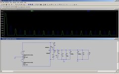
Have a look at this sim.
I included the winding resistance in the source for the transformer I'm considering.
I found this white paper that addresses the issue. I have not read it, I only looked it over.
There are some useful calculation in the paper.
http://www.newark.com/pdfs/techarticles/epcos/inrushCurrentLimiters.pdf
You can use a NTC thermister or a large power resistor in series with the transformer primary.
Bypass the series element with a relay after the the first few cycles.
The relay can be activated by the supply Voltage if you use say a 48Vdc with a series resistor on the coil. That simple.
David.
Attachments
Last edited:
I've seen posts suggesting the primary resistor with timed relay short is a better idea than the thermistor due to power bumps on the mains. If you have a short power bump the transformer comes back on with the thermistor still hot and you get (near) full inrush.
Hi agdr,
This is true. But if you bypass the thermistor with a timed relay then this solves the problem since the thermistor is only active for a short time.
David.
you can put a limiting resistor in series with your transformers' primary....
if you use a 10 ohm 50 watt resistor say, then you limit your inrush currents to not more than 24amperes if you are using a 240 volt primary and 12 amps when using 120 volt supplies...
make sure you short out this resistor with a time delay relay set to about 3 seconds...
if you use a 10 ohm 50 watt resistor say, then you limit your inrush currents to not more than 24amperes if you are using a 240 volt primary and 12 amps when using 120 volt supplies...
make sure you short out this resistor with a time delay relay set to about 3 seconds...
This is true. But if you bypass the thermistor with a timed relay then this solves the problem since the thermistor is only active for a short time.
Hello David,
Good thought, but I'm not sure that would solve it. Lets say the mains power bump lasted for 500mS but the thermistor remained hot enough to be in a low resistance state for 1 second. If the timed relay was 300mS then the power would be re-applied at 500mS while the thermistor was still "hot" and low resistance, and would remain that way through the 300mS relay delay (700mS total since power failed) until the relay shorted out the termistor.
Some of my assumptions there may certainly be off though, especially on how long the thermistor remains hot enough to be low resistance.
")
Last edited:
In this situation the caps would probably still be partially charged and hence capacitive inrush should be less, that is however not saying anything about the magnetic inrush current.. A time relay and fixed resistor might be slightly more reliable if sags and dips are a common occurrence in your neck of the woods.
Hello David,
Good thought, but I'm not sure that would solve it. Lets say the mains power bump lasted for 500mS but the thermistor remained hot enough to be in a low resistance state for 1 second. If the timed relay was 300mS then the power would be re-applied at 500mS while the thermistor was still "hot" and low resistance, and would remain that way through the 300mS relay delay (700mS total since power failed) until the relay shorted out the termistor.
Some of my assumptions there may certainly be off though, especially on how long the thermistor remains hot enough to be low resistance.
There are some variables to this argument. Whether one approach would work better than the other depends largely on the the design, components selected. The size of the capacitors, the cold and hot resistance of the thermistor etc. One should put it all to test on the bench before making a decision on which is better.
My experience with thermistors used in this application is that it takes 5 to 10 seconds before the thermistor reaches a temperature uncomfortable to touch. About 70 deg C.
Not that one should ever touch the thermistor because the oil from our fingers causes the casing to crack.
I don't think the occasional power bump is that big a deal but repeated bumps....
David.
- Status
- This old topic is closed. If you want to reopen this topic, contact a moderator using the "Report Post" button.
- Home
- Amplifiers
- Power Supplies
- calculating inrush to a capacitor bank