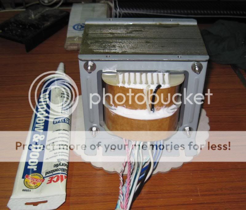
here is a newly built power traffo for a tube amp,
center leg is 1 3/4 and stacked to about 3 inches....
i rate this traffo at about 600volt-amperes...
i use a silicon sealant to seal off the edges of the windings to prevent moisture ingress,
the white sealant dries clear, it will take about a week for the entire traffo to be
fully dried and ready for service, prior to that i will do an open and short circuit test
to compare design data with actual conditions....
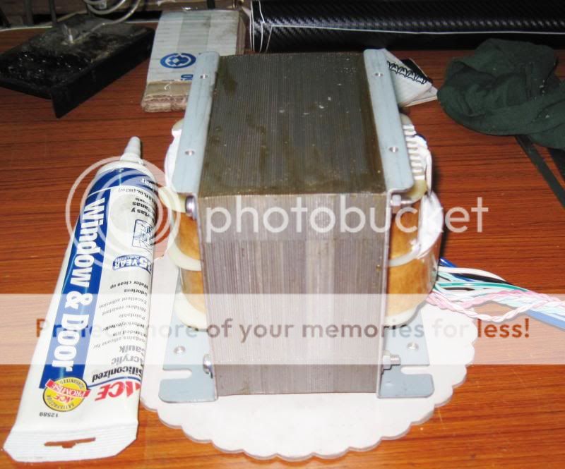


I hope it is a neutral cure silicon sealant you have used. Some of them give off acetic acid during the cure phase and could attack the copper windings.
Saying this I used the wrong one to pot up an EHT tripler in a scope many moons ago but I applied it in thin layers waiting for each to go off before adding the next. It is still going strong after all these years.
Hopefully yours will be OK too and give you many years of service.
Saying this I used the wrong one to pot up an EHT tripler in a scope many moons ago but I applied it in thin layers waiting for each to go off before adding the next. It is still going strong after all these years.
Hopefully yours will be OK too and give you many years of service.
I hope it is a neutral cure silicon sealant you have used. Some of them give off acetic acid during the cure phase and could attack the copper windings.
Saying this I used the wrong one to pot up an EHT tripler in a scope many moons ago but I applied it in thin layers waiting for each to go off before adding the next. It is still going strong after all these years.
Hopefully yours will be OK too and give you many years of service.
this is a non smelly type and shrinks as it cures, that is why it is okey to apply
in a bulging manner, it dries clear as well.....and most of all it is cheap to buy, very DIY friendly....
and you can use your fingers to form it, it is water soluble as well...
My rant/soap and input to this wonderful arena
What advantages or dissadvantages would placing a gap of x distance and y area have? I say y area because not all traffo gaps are total cross sectional core gaps. I know it would cause Bmax to increase thus inversly proportional to inductance. But what kind of core/copper losses would one encounter? To overcome the inverse proportions, by how much would one have to increase the # of windings? What generic core materials are/have been scavenged to plug-into some of these dynamic calculations? I have several transformers that I would like to know more about and instead of playing 21questions about each and every one that I have or would like to have (be it NOS, or purchased).
#RANT# Also what I have noticed is the fact that there are some DIYaudio members (Label:Troll) that instead of researching this vast topic of Electromagnetics, they tend to just pop-in a thread asking, "I have this square-ish heavy iron thing. Blah, Blah. I want to power my diy 500W amp. Do the math for me so I dont have to think about how I can get electrocuted rewinding it." A good bit of reading, power-searching, lengthy calculations that comprise an excellent/well built durable transformer will do more for your knowlege/experiance than for someone to do the brain-stuff while you go unashamedly "hands-on" with little to no knowlege. #END#
I am currently working on a semi-full featured spreadsheet that hopefully encompasess a good majority of transformer design calculations. I am trying to gather information that will lead to:
1) Assist in new constructed power transformer
2) Assist in estimating a reverse engineered on-hand transformer
3) Assist in gaining knowlege and respect for this facet of electrical/electronics
4) Assist in arming an individual with knowlege to determin if it is worth his/her time/effort/$$
5) I would like to include calculations without vast amount of explaination that includes Core material/frequency/Voltage/Current/Wire. (I am not sure if all this is possible given my current knowlege/understanding. However, I am willing to undertake this lengthy process.)
The toughest part of this so far is muddeling through the various "intrinsic"/"brute force"/"simplistic" calculations. I have already encountered 5 websites, 2 pdf's, 3 forum threads, and 1 blog that have either erronious/false/misleading information or they oversimplify the information needed. One fine example was one that I actually entered real information into a spreadsheet and it spit out a result of Turn/V=9e14, this was for a 480VA/120Vin-80Vout at 95mT!?! Another example was a short web page that basically described the losses within a transformer a function solely reliant on wire resistance vs. (current arbitrairly chosen according to awg). My definition of Powersearch = 4 -5 instances of IE with 8-15 tabs each. And away we go!!!
I hope it is a neutral cure silicon sealant you have used. Some of them give off acetic acid during the cure phase and could attack the copper windings.
Saying this I used the wrong one to pot up an EHT tripler in a scope many moons ago but I applied it in thin layers waiting for each to go off before adding the next. It is still going strong after all these years.
Hopefully yours will be OK too and give you many years of service.
I notice he used the "cheap stuff" with the 5 year warranty. The better kind says 35 years on the tube. But this is better or worse for its intended purpose of outdoor weather sealing. The cheaper stuff might be better in for use with transformers.
This 5 year caulk is really not silicon seal. it is more like very think latex paint in the tube. There is silicon mixed in the acrylic but I suspect it is already cured and made into a powder and mixed into the acrylic.
I use this kind of caulk outdoors on projects that I want to cover with paint. I can put it on then smooth it with a wet towel as it is water soluble until it cures.
Another question that pohed-in my head. If a double "C" core were to be placed side-by-side without overlaping, and the Primary and secondary were to be wound on the newly created "center leg" producing a "quasi" EI. Would the calculations need to include an aditional "gapping factor"? Or would the 2 central legs be considdered 1 center tounge?The reason I ask is that I have noticed the lines of magnetic flux have been diagramatically shown to traverse through that area perpindicular to the coils and not cut through the cohersive force of the mag lines. What of eddy currents? Would they increase or decrease? I used to have several ballasting transformers that were "T&L" sections (deep in the dump by now).
Best two things I've found for transformer design are:
Magnetics Designer Manual pdf [especially if you like maths, even the formulae to calculate leakage inductance and inter winding capacitances are contained therein, although I would think any such calculation could possibly be inaccurate, one of them is an integral of an integral of an integral !!]
and
High Reliability Magnetic Devices by McLyman [which contains the most practical winding techniques I've seen..in a book, good diagrams etc].
Sad to say I have mastered neither.
Specifically for audio is Pat Turner's website.
Another question that pohed-in my head. If a double "C" core were to be placed side-by-side without overlaping, and the Primary and secondary were to be wound on the newly created "center leg" producing a "quasi" EI. Would the calculations need to include an aditional "gapping factor"? Or would the 2 central legs be considdered 1 center tounge?The reason I ask is that I have noticed the lines of magnetic flux have been diagramatically shown to traverse through that area perpindicular to the coils and not cut through the cohersive force of the mag lines. What of eddy currents? Would they increase or decrease? I used to have several ballasting transformers that were "T&L" sections (deep in the dump by now).
yes, but you can get away with higher flux density, the mating surfaces need to very smooth...
yes, but you can get away with higher flux density, the mating surfaces need to very smooth...
no, it is not generally possible to configure tape wound cores anyway other than the way they were designed.
also, my choke and transformer design spreadsheets have been updated
Index of /bulk/spreadsheets
.xls versions should work, but i don't trust them... just download open office...
Hi, Tony, would it make sense to use laminated UI-core to make a balanced PP trafo ?
yes, although i haven't seen one and laminates are hard to come by at least here in my place...
And now I know where these "constants" come from....... duhn-tah-dah... ONLY if you have a scavenged ^2 core! That is why my calculations and my confusion was soo irkish. Several calculations were really bad. Read 2 "how-to's" that was somewhat informative and 1 diyAudio thread. It was all fine and dandy untill actual variable input time. One how-to stated "(CoreArea)cm^2 * 0.2112 = Turns ratio", and the other 'how-to' stated "and multiply by a constant of 42 = Max flux density" . No explaination was given on what thoes constants were, nor how they were derrived, as if by  . Funny thing is both plainly stated thoes formulas to be the "accepted" design methodology.
 The diyAudio member posted a formula that did the same except he used the constant of '50' to achieve Bmax, I will say that he did say that he could not remember where it came from as it was a long time ago in shool. Found the '42' info as bobbin information in the pdf titled 'Manual Per Il Calcolo Di Transformatori'. I then went back to the first how-to and plugged-in some arbitrary #'s and *poof* there it was. Referincing that pdf, I now see that a true ^2 core would be easier to calculate. However, not all scavenged EI transformers are ^2. Meaning the ^2 calculations become meaningless unless you
  modify that particular scavenged core into a ^2 core. Most of the transformers that I have seen have stacks thicker than the tounge width, which means modification to a square core = removal of laminations which inturn = less available VA for a cool/safe operating transformer. Insertion of real #'s into the ^2 formula makes me wish it were that easy for all configurations.
Thank you Johansen for the added info.
. Funny thing is both plainly stated thoes formulas to be the "accepted" design methodology. The diyAudio member posted a formula that did the same except he used the constant of '50' to achieve Bmax, I will say that he did say that he could not remember where it came from as it was a long time ago in shool. Found the '42' info as bobbin information in the pdf titled 'Manual Per Il Calcolo Di Transformatori'. I then went back to the first how-to and plugged-in some arbitrary #'s and *poof* there it was. Referincing that pdf, I now see that a true ^2 core would be easier to calculate. However, not all scavenged EI transformers are ^2. Meaning the ^2 calculations become meaningless unless you modify that particular scavenged core into a ^2 core. Most of the transformers that I have seen have stacks thicker than the tounge width, which means modification to a square core = removal of laminations which inturn = less available VA for a cool/safe operating transformer. Insertion of real #'s into the ^2 formula makes me wish it were that easy for all configurations.Thank you Johansen for the added info.
yes, but you can get away with higher flux density, the mating surfaces need to very smooth...
That should require each side to be well matched for all mating surfaces. That is unless someone actually wants a gap or two or three.....
no, it is not generally possible to configure tape wound cores anyway other than the way they were designed.
Phisically, yes anyone should understand this in the case of strip-wound and especially torroid cores. As the sides would be curved and subject to being at best oval in shape. Thus only a small fraction of both cores would be 'coupled'. From that point extending 'up' and 'down' the distance between the cores would increase = more wire (meanlength) = compounded losses. Agreed that would be bad, very bad.
However, would IE(ish) laminations be subject to the same? I presumed by glancing over the multi-phase designs that mutual Mg-inductive coupling of cores would be possible. One should realize that without actual calculations or proven design, one should always presume worst case losses (aka. FIRE!). I noticed in a previous posting this thread, Tony received a donated amp opt that looked similar to a multi-phase trafo. He split it for 2 separate opt's.
Index of /bulk/spreadsheets
.xls versions should work, but i don't trust them... just download open office...
link is inaccessible. 403-forbidden
tbh, i never needed any spreadsheet in my traffo builds.....
but no one is stopping you from making and using one,
i am simply not interested....i have all i need....
a pen and a piece of paper and a calculator is good enough for me...
45 years or so ago while working on my first traffo build,
i let the magic smoke come out...
lesson learned, never recycle copper wires from an old
traffo.....only the iron can be reused....
and ever since that learning episode, i never had a traffo
that i built burn out on me...
we all learn from our mistakes,
and there are a lot of things to be learned from actual experience
that can never be found in books....
even if you pick my brains for free, that is no guarantee of learning,
i believe it is those things that i am not saying are what you actually need...
doesn't matter much, it is the core area under the windings that figure in the calculations,
as for cores, there are scrapless, non standard EI's, C cores and torroids...
This would be true for the unassuming/prediction of estimating. However, to the unaware a scrapless punched laminate is physically different size than a non-scrapless punched laminate. More specifically, if any one calculation has a pre-defined integer you would need to double check the calculation, as I have encountered at a minimum of 5 different calculations giving at least one of the variables a 'concrete' integer. True example I have seen uses this 'static': [ref1] "Read: area is equal to the constant * multiplied by the square root of the power of the transformer. where * = 0.8 if the kernel is fine and 1.2 If the core is of inferior quality. We normally take 1. The result is obtained in cm2 and is the rectangular core area marked in blue in the figure." This may hold true for scrapless laminates but it does not hold true for non-scrapless "scavenged" cores that one may have sitting in the attic. I have repeatedly pluged actual #'s into equasions such as this and ended up tossing it to the "well that is THEIR design, with NEW laminations" criteria. I actually have a representitive Triad-Utrad transformer on hand that is rated 115V/50-60Hz/35Vct @ 10A, which gives a measured unloaded Vout of 29Vac, that I am using as a referrence. Might be a bit old but definitly one that I have had in hand for a # of years. I measured this core and lams and window and wire guage, and overall dimensions, used a stacking factor of ~90% and a low grade steel asumption (thick lam sheet). Calculation of the Triad core and compairing it to the calculation of the aformentioned website were at a minimal of 30% different. Not only is my core larger, but the window is way, way larger. In sumation, indeed using real #'s has a infitesimal advantage over subsequent 'what-if, because I have nothing in hand'. So as to the 'it does not mater much', Tony I would agree to the extent that so as long as it is understood that thoes calculations are for scrapless designs. And dissagree to the extent that if the design is a non-scrapless design it does matter. I have the pdf that gives 2 seperate core area and TPV equasions for this (one of the 20 or so). I agree also that a pen and paper is indespensible as well as never reusing unwound wire (safety should be first). The spreadsheet usage would be a 'quickie' way of 'what have I really got' estimation for thoes of us DIYers that are using an already made transformer, but would like to know what kind of aditonal work would be involved from modifying one.
[ref1]Calculo de Transformadores
google translate was used.
Last edited:
we all learn from our mistakes,
and there are a lot of things to be learned from actual experience
that can never be found in books....
even if you pick my brains for free, that is no guarantee of learning,
i believe it is those things that i am not saying are what you actually need...
 Yeuppers. There is 2 types of people in the world. One wakes up and starts each day with one more day of experiance, and the other wakes up for 20 years with one day experiance. Replacement of experiance is not an option.
Last edited:
magnetizing current is inversely proportional to mean magnetic path lenght...https://www.google.com.ph/search?q=...57&sourceid=chrome&espv=210&es_sm=93&ie=UTF-8
so that non scrapless laminates can have smaller or larger depending on actual dimensions for same size center leg...
chapter 5 of RDH4, page 235 (http://www.ax84.com/static/rdh4/chapte05.pdf) gives the formula that i use in my designs and builds,
VA = (A*5.58)^2 volt-amperes
where A is the area under the core in square inches
hardlinks:
you should be able to browse the directories as well
http://johansense.com/bulk/spreadsheets/tranformerdesign1.ods
http://johansense.com/bulk/spreadsheets/choke%20calculator.ods
regarding magnetizing current... all that matters is magnetizing VA which is given from the manufacturere at volt amps per kilogram, typically single digit.
watts lost per kilogram at 1.7T for good toroidal flux is on the order of one watt.
so, really, all this wasted time of calculating from archaic formulas is really just.. meh, do i want a 30C temperature rise or 120? can i sell the completed transformer for 6 dollars a pound or 30?
I would like to get my spreadsheet to output a graph of efficiency vs load for various flux densities.
also, i've found that taking a part transformer cores and putting them back together easilly doubles the iron loss and magnetizing VA, due to all the scratches in the insulating coating.
- Home
- Amplifiers
- Power Supplies
- Tony's latest traffo DIY build