Hi Tony,
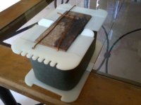
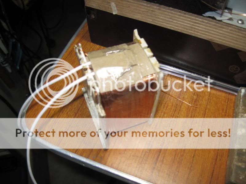
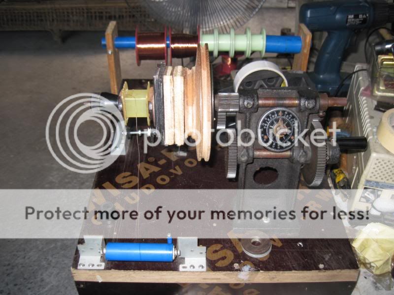
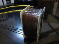
Here's my progress report of 2nd traffo with core 1 & 3/4" stacked to 3.6" having primary winding #turns 246 used about a kilo of #16 magnet wire. Planning to use for F5T. Hope to do secondary this weekend")
looking good Roland....
Hi All,
I research some OPT for pentode and see that they have the Screen Feedback Winding. This is the separate winding from the primary, one tap to B+ and other tap to screen. As I thought, this is a kind of feedback winding, and same purpose with Ultralinear tap. But after hearing, the sound with screen winding seem better than using Ultralinear.
I search google but there is lack of information about this (way to calculate the turns, wire diameter, etc…), so is there anybody can help me to get it?
Thank you very much.
some kindhearted members in another forum donated to me a Luxman LV-103 and an LV105 to play around with....they are Japanese pier units and therefore run on 100 volt mains.....as i am forever afraid of Murphy, i decided to convert them to 230 volt mains instead...
both the LV-103 and the LV105 use the 6CG7 tube long tail pair as VAS to drive the lateral mosfet output stage. a separate small power traffo is used to light up the filaments.....since the 6CG7, (a 9pin analogue of the 6SN7), likes better to run on higher plate voltages, i have decided to replace them with 6dj8 type tube, but this is another story altogether...
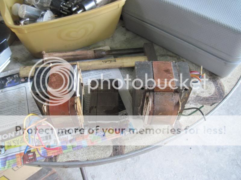
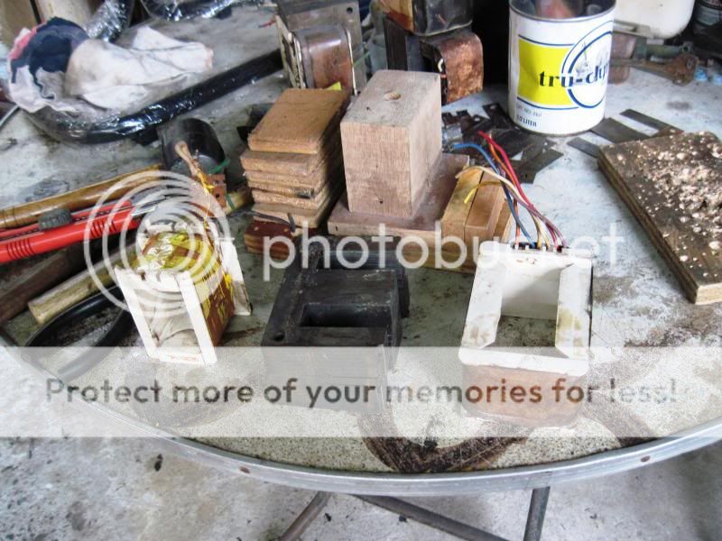
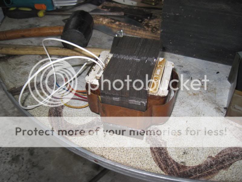
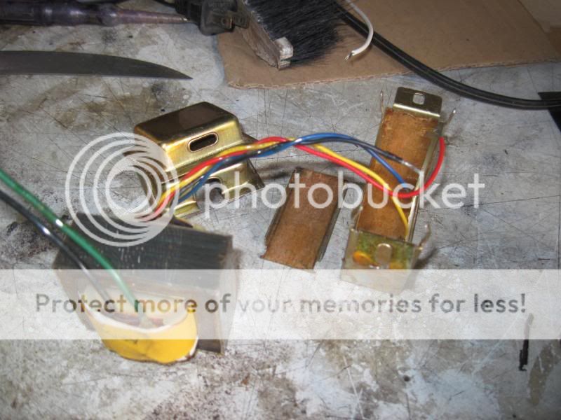
main power traffos removed:
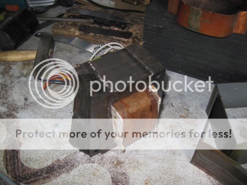
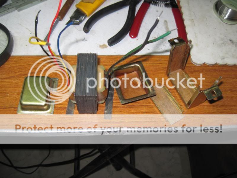
an angle grinder was used to remove the welds on the side of the power traffos to separate the E's from the I's...prior to grinding these 2 traffos were completely immersed in a tub full of lacquer thinner for 2 weeks.....
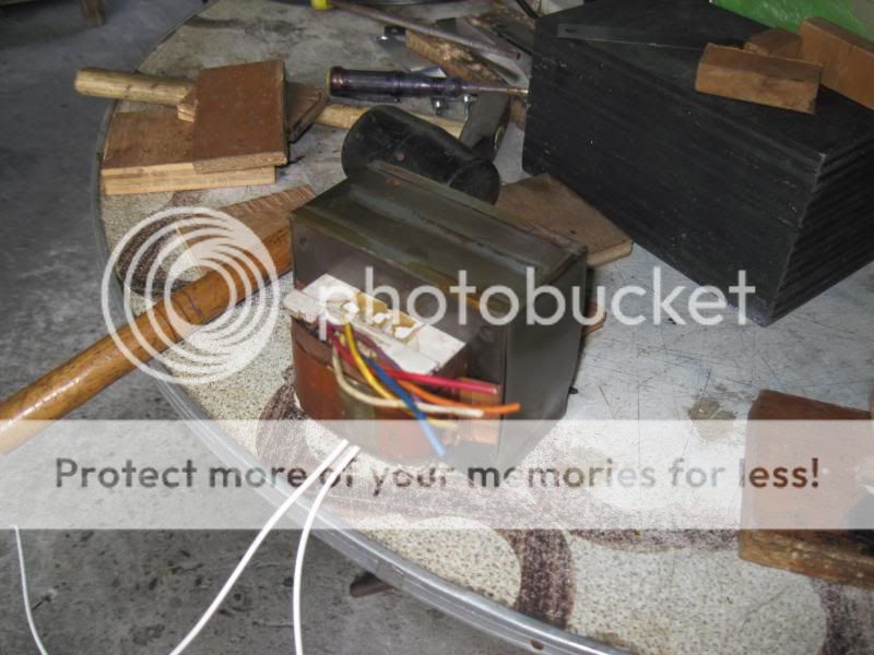
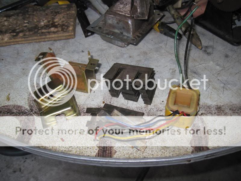
with the coil assembly yanked out of the core, the bobbins were pried open to separate the primary and secondary chambers.....these traffos have completely separate primary and secondary chambers so that only the primary coils is changed...the secondary coil assembly is left untouched...
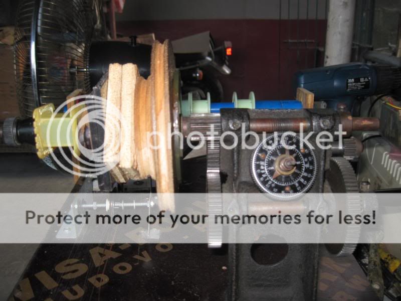
so the primary coil is put on my winder to count the number of turns which turned out to be 220 turns of #19 magnet wire, therefore at 230 volts this becomes 506 turns of #23 wire...
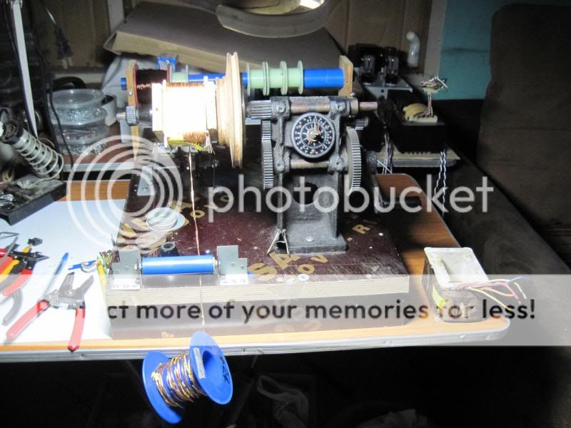
then comes the windup for the 230volt primary...
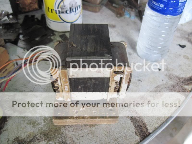
once done, installing the E and I's comes next....since i do not have access to tig welding, i decided to do the traditional interleaving, but first the weleded edge must be grinded to make it easy to separate the laminations...
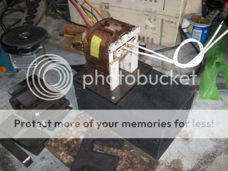
the E's completed...
inserting the I's...
finally inserting the copper banding, mu-metal wrapping and mounting brackets installed completing the job..
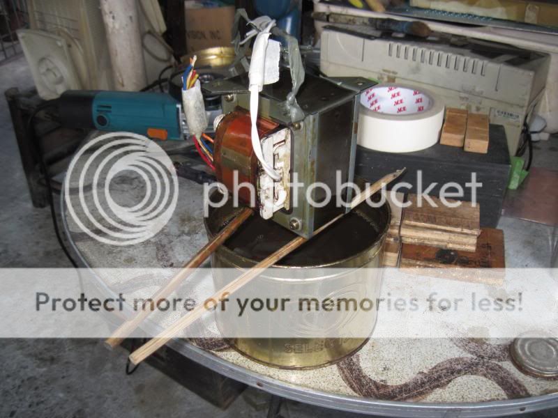
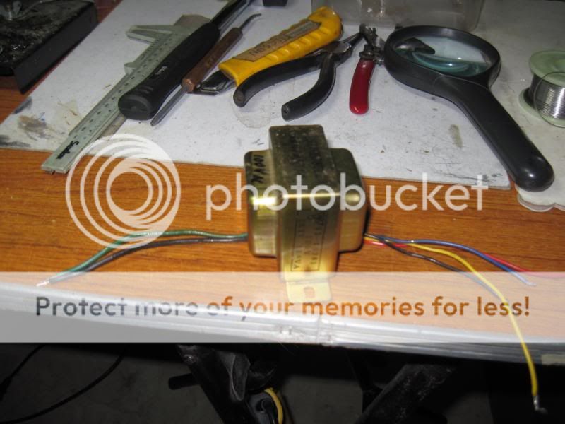
completed traffo is immersed into a tub of clear air drying polyurethane electrical varnish..
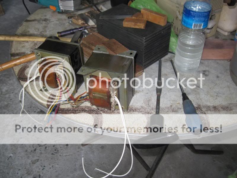
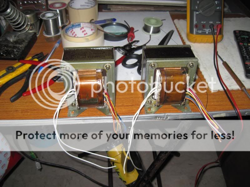
completed traffos ready for action...
both the LV-103 and the LV105 use the 6CG7 tube long tail pair as VAS to drive the lateral mosfet output stage. a separate small power traffo is used to light up the filaments.....since the 6CG7, (a 9pin analogue of the 6SN7), likes better to run on higher plate voltages, i have decided to replace them with 6dj8 type tube, but this is another story altogether...
main power traffos removed:
an angle grinder was used to remove the welds on the side of the power traffos to separate the E's from the I's...prior to grinding these 2 traffos were completely immersed in a tub full of lacquer thinner for 2 weeks.....


with the coil assembly yanked out of the core, the bobbins were pried open to separate the primary and secondary chambers.....these traffos have completely separate primary and secondary chambers so that only the primary coils is changed...the secondary coil assembly is left untouched...

so the primary coil is put on my winder to count the number of turns which turned out to be 220 turns of #19 magnet wire, therefore at 230 volts this becomes 506 turns of #23 wire...

then comes the windup for the 230volt primary...


once done, installing the E and I's comes next....since i do not have access to tig welding, i decided to do the traditional interleaving, but first the weleded edge must be grinded to make it easy to separate the laminations...

the E's completed...

inserting the I's...

finally inserting the copper banding, mu-metal wrapping and mounting brackets installed completing the job..


completed traffo is immersed into a tub of clear air drying polyurethane electrical varnish..

completed traffos ready for action...

more transformer porn ...ahh, ohh, ahh, ooooooh
did not know Japanese supply was only 100 V .. why not just put together a large
step-up up transformer .. you wanted to see EXACTLY how they were wound right ?
I REALLY need to get my winder built. Still waiting on parts.
I have some base metal [mild steel lams] which I am going to use for mains inductors, would I need to varnish them since mostly dc and relatively low voltage drop as well ?
Have you ever had problems air drying them like that. The books say they should be cured at 200 celsius for ten hours, I know it is hot in Manila but it isn't THAT hot, apart from the LRT at rush hour.
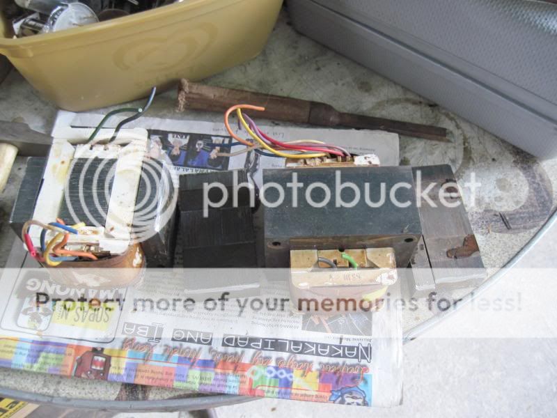
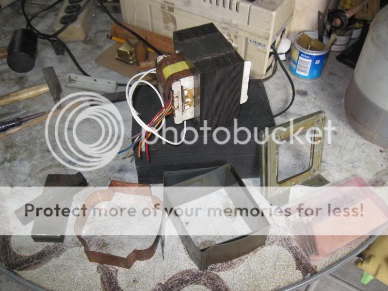
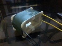
there is a 2nd smaller traffo and is used to power the tube filaments...
it is likewise converted to 230 volts..
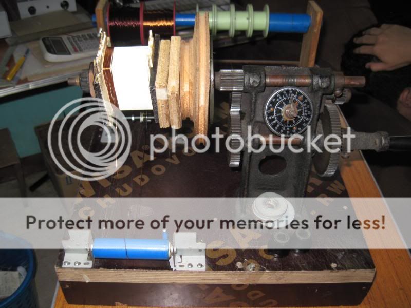
primary turns are counted on the winder...
there were 1008 turns of #30 wire counted, to convert to 230vac,
i wind 2600 turns of #35 for primary coil..
secondary windings have two coils of 170 turns each of #25 magnet wire..
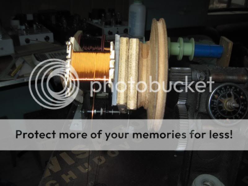
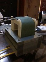
winding new primary coil...
reinserting the E-I's..
finally putting back the endbells and brackets...
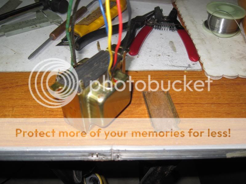
completed traffo...
it is likewise converted to 230 volts..


primary turns are counted on the winder...
there were 1008 turns of #30 wire counted, to convert to 230vac,
i wind 2600 turns of #35 for primary coil..
secondary windings have two coils of 170 turns each of #25 magnet wire..

winding new primary coil...

reinserting the E-I's..

finally putting back the endbells and brackets...

completed traffo...

Oh man, that is gorgeous work.
I am starting out trying to wind a trafo.
I decided - maybe erroneously I should wind a Microwave transformer and do so without disassembling the EI's.
Now your EI core was welded but not interleaved ? I will check how mine is. It would be interesting to see what it is, I can weld it back of I had to.
I am only winding a 35 turn secondary, so maybe its not so bad to wind it without cutting it open.
Thanks.
Srinath.
Now your EI core was welded but not interleaved ? I will check how mine is. It would be interesting to see what it is, I can weld it back of I had to.
I am only winding a 35 turn secondary, so maybe its not so bad to wind it without cutting it open.
Thanks.
Srinath.
no, it was not interleaved....there are many examples in youtube....Easiest MOT Salvage Tutorial Pt.1 - YouTube
If I pulled my traffo apart by grinding off the welds and instead of welding it back together, I can drill holes in the corners and bolt it with a bar across it then will it not have a proper magnetic field distribution ?
I am hoping to not try interleaving as my first experience. Thanks for all the knowledge.
Cool.
Srinath.
I am hoping to not try interleaving as my first experience. Thanks for all the knowledge.
Cool.
Srinath.
In the transformer that I removed both the primary and secondary, the EI's have been welded in 4 lines. Like they would be if the EI's were stacked "EI" and "I Reverse E".
It also has the bottom plate plug welded into the plates on the one side where 1 pair of EI welds are. The stupid thing is, its not interleaved. Its all well "non interleaved".
The one I plan to use without pulling the primary apart has 1 set of EI welds and its not on the same side as the bolting plate.
I wouldn't be pulling it apart. 35 turns I can wind by hand.
Cool.
Srinath.
- Home
- Amplifiers
- Power Supplies
- Tony's latest traffo DIY build