looks nice , do u have turn counter too ?
thanks,
i dont have turn counter,
after i wind and checking turns . this wires are thick, so counting turns not hard, but small wires problem counting turns.
hi tony,
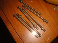
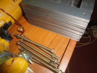
is this bolt and nuts perfect for lamination tightening?
it is galvanized bolt and nuts. 4 inch long.
is this bolt and nuts perfect for lamination tightening?
it is galvanized bolt and nuts. 4 inch long.
Attachments
hi tony,
is this bolt and nuts perfect for lamination tightening?
it is galvanized bolt and nuts. 4 inch long.
yes, that will do.....look for shoulder washers to use with your bolts and nuts, better to use them for cooler running traffo...
An externally hosted image should be here but it was not working when we last tested it.
hi tony,
i am busy these days, because last days i am in my wife place,
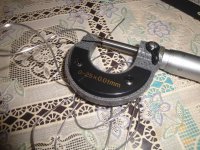
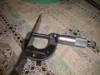
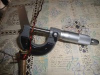
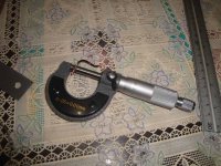
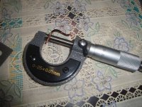
i am facing a big problem with wire gauges, i didn't ask wire size in mm, when i buy magnet wires, i asked in gauges, today i bought a micro mm measurement tool and measured the gauge no-15 it shows 1.80mm, i checked the supplier chart and it shows 1.80mm, in ur chart, shows 1.45mm,
i already told u gauge no-13 hard to wind, i checked that one also, micro mm measurement tool shows 2.25mm , in ur chart showing 1.90mm.
i already wind secondary 42turns into 4 with 1.80mm gauge wire, i didnt wind primary yet,
so can u help me to solve this problem.
i am busy these days, because last days i am in my wife place,
i am facing a big problem with wire gauges, i didn't ask wire size in mm, when i buy magnet wires, i asked in gauges, today i bought a micro mm measurement tool and measured the gauge no-15 it shows 1.80mm, i checked the supplier chart and it shows 1.80mm, in ur chart, shows 1.45mm,
i already told u gauge no-13 hard to wind, i checked that one also, micro mm measurement tool shows 2.25mm , in ur chart showing 1.90mm.
i already wind secondary 42turns into 4 with 1.80mm gauge wire, i didnt wind primary yet,
so can u help me to solve this problem.
hi tony,
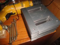
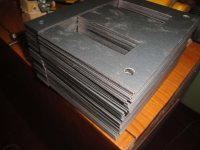
lamination thick is .5mm.
i remove the enamel and measure the wires.
lamination thick is .5mm.
i remove the enamel and measure the wires.
Attachments
Last edited:
hi tony,
i am busy these days, because last days i am in my wife place,
i am facing a big problem with wire gauges, i didn't ask wire size in mm, when i buy magnet wires, i asked in gauges, today i bought a micro mm measurement tool and measured the gauge no-15 it shows 1.80mm, i checked the supplier chart and it shows 1.80mm, in ur chart, shows 1.45mm,
i already told u gauge no-13 hard to wind, i checked that one also, micro mm measurement tool shows 2.25mm , in ur chart showing 1.90mm.
i already wind secondary 42turns into 4 with 1.80mm gauge wire, i didnt wind primary yet, so can u help me to solve this problem.
that is because in India the British standard applies, while in Manila we use the American standard.....
so better get wires based on my table on diameter in mm....
hi tony,
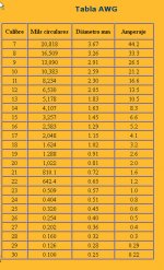
why this no-13 gauge different from both images. only no-13 is different.
in post no-199 u mention no-13gauge for secondary , is it 1.83mm or 1.90mm?
because in the images two charts showing two values,
so no-1.83mm is ok, can i use 1.80mm gauge, because in here 1.83mm is not available.
why this no-13 gauge different from both images. only no-13 is different.
in post no-199 u mention no-13gauge for secondary , is it 1.83mm or 1.90mm?
because in the images two charts showing two values,
so no-1.83mm is ok, can i use 1.80mm gauge, because in here 1.83mm is not available.
Attachments
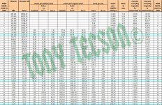
you are better off with diams in mm as a guide.....as i have kept on repeating, we are not using the same standards wrt copper wire sizes...diameters vary because of insulation thickness there are copper wires that are single, double insulated, still others come with 5x insulations so naturally diameters vary......you don't worry about those things so much.... your goal is to stick those windings in....
you need a bobbin sized for 1 3/4 centre leg stacked to 4 1/2.....
you can get around 1740 volt amperes out of this...
primary turns = 233 turns #16 AWG magnet wire
secondary turns @30volts = 30 turns #13 AWG magnet wire, 4 coils, two bifillar windings....
in my country, the standard is AWG, please take note of this as you may have a different one in yours...
so i go to this transformer,
1.80mm for secondary and for primary 1.25mm.
If you have not bought the 1.8mm wire then consider winding both the primary and the secondary with the 1.25mm diameter wire.
Use dual turns for the secondary. This gives the equivalent of double the copper cross sectional area.
You will find it much easier to wind with 1.25mm wire.
Use dual turns for the secondary. This gives the equivalent of double the copper cross sectional area.
You will find it much easier to wind with 1.25mm wire.
Tony, sorry for hijacking the thread [again].
just wondering if anyone has a copy of Reuben Lee's 50's book from t'internet ?
trying to understand the power transformer specification sheet on page 78.
there are various calculations most of which are fine but I cannot see where he is getting the secondary VA of 220 VA, specifically the current part of .081 amps [per volt value ?].
also he seems to be averaging the VA for some strange reason ?
also at bottom left of specification he has 1390 volts ac which miraculously morphs into 1252 volts dc, after which various voltages are deducted for losses etc.
he is putting it through an inductor per the spec but I thought you multiply ac voltage 0.707 when it goes through an inductor, or is it dependent on the value of the inductor ?
if anyone could throw some light much appreciated.
Tony how long does it take you to design one of your transformers on average, do you use a computer program or pencil and paper, do you follow p. turner's site ?
Tony, sorry for hijacking the thread [again].
just wondering if anyone has a copy of Reuben Lee's 50's book from t'internet ?
trying to understand the power transformer specification sheet on page 78.
there are various calculations most of which are fine but I cannot see where he is getting the secondary VA of 220 VA, specifically the current part of .081 amps [per volt value ?].
also he seems to be averaging the VA for some strange reason ?
also at bottom left of specification he has 1390 volts ac which miraculously morphs into 1252 volts dc, after which various voltages are deducted for losses etc.
he is putting it through an inductor per the spec but I thought you multiply ac voltage 0.707 when it goes through an inductor, or is it dependent on the value of the inductor ?
if anyone could throw some light much appreciated.
Tony how long does it take you to design one of your transformers on average, do you use a computer program or pencil and paper, do you follow p. turner's site ?
the calculation sheet predicts the dc output voltage across the load...instead of the factor 0.707, he used 0.664 ......
there were 2 secondary coils each rated to provide 110va so the total secondary va adds up to 220va...
i see nothing unusual in the calculation sheet, you just need to digest it by reading it again and again... i might even adopt it.....

because of experience i can design transformers in a matter of minutes having been already familiar with materials available to me........i use pen and paper method
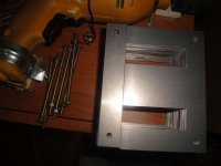
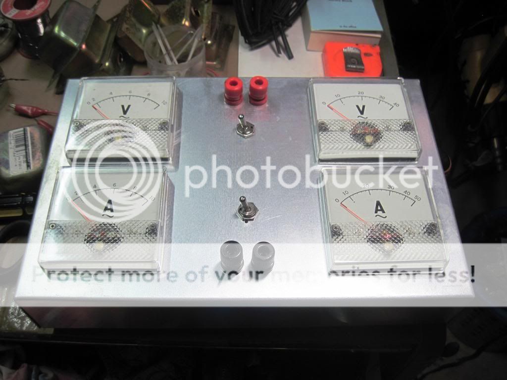
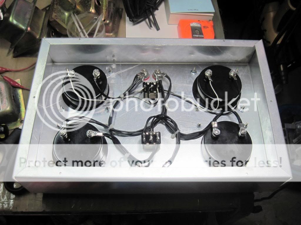
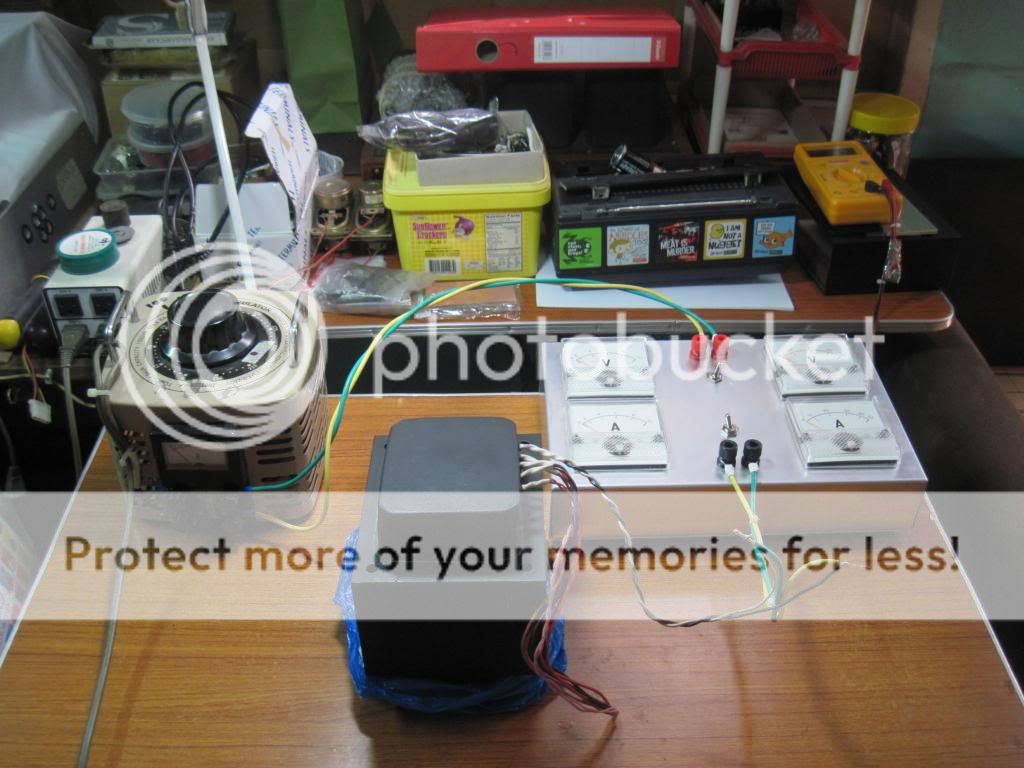
traffo testing:
this is the traffo under test:
center leg of 2 inches stacked to 3 3/4 inch thick, core rating as per RDH4 is about 1750volt-amperes,
the traffo has since been finished with "poly-tuff" automotive filler and painted matte black.....
the purpose of this post is to demonstrate the open circuit(core loss) and short circuit(copper loss) testing of power traffo
to find out efficiencies under load, currents from 1A to 7A were used....
although core rating is 1750VA, i will rate this traffo as a 1200watt power traffo....

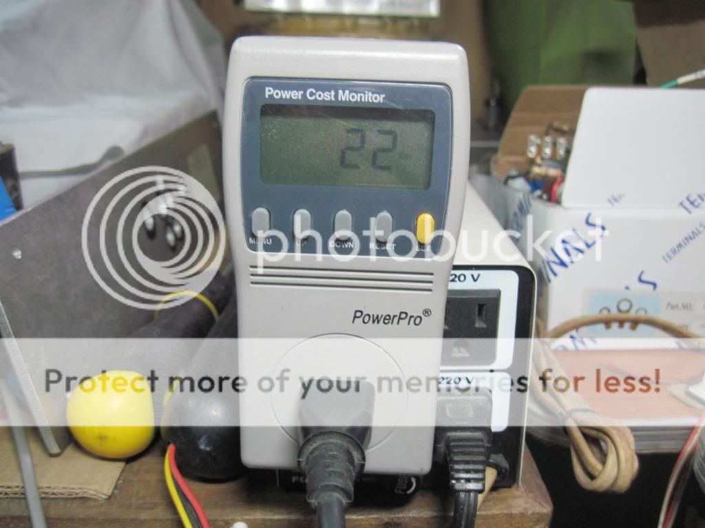
no load or open circuit testing using a kill-a-watt tester, in this test all secondaries of the traffo are left open...
no load current:
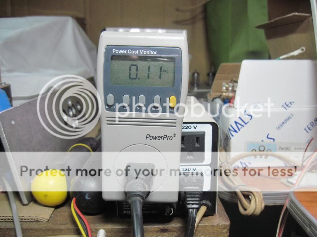
no load energy stored:
short circuit testing or copper loss test:
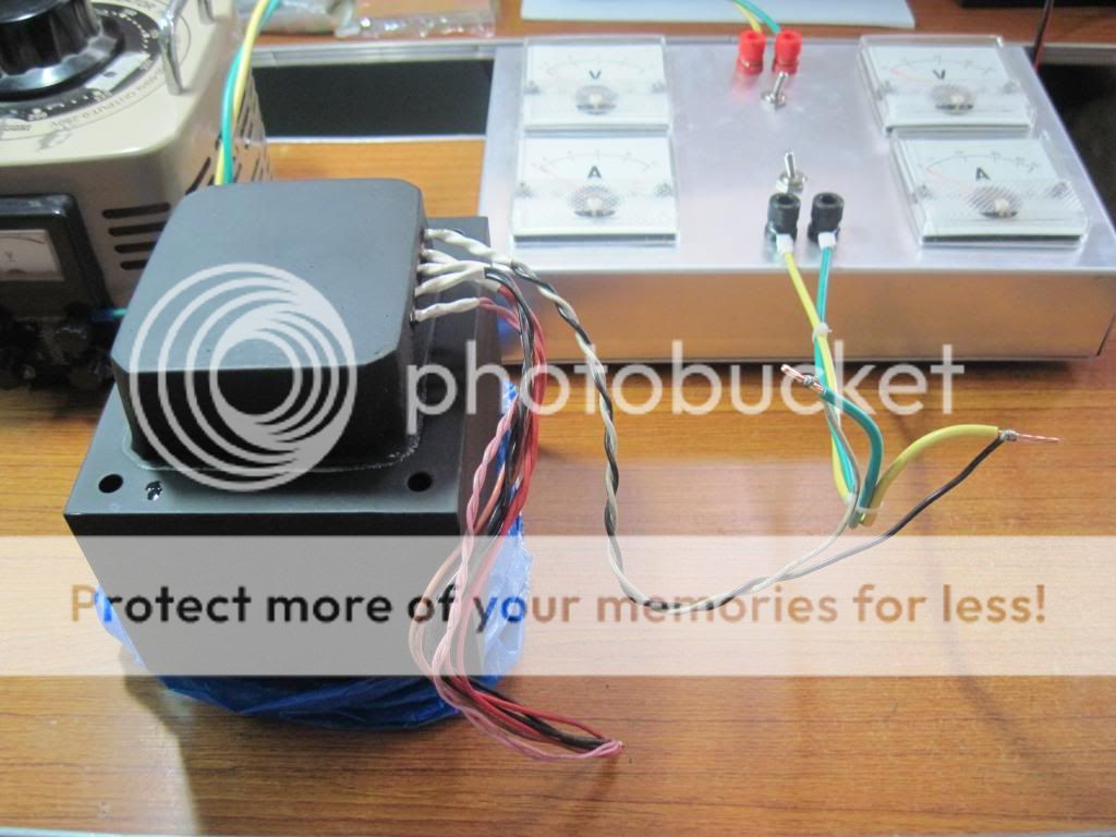
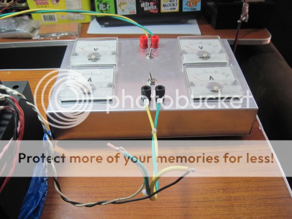
in this test all secondary winding's are joined together to form a short, a variac and my test contraption is used,
testing at several point from 1A to 7A....
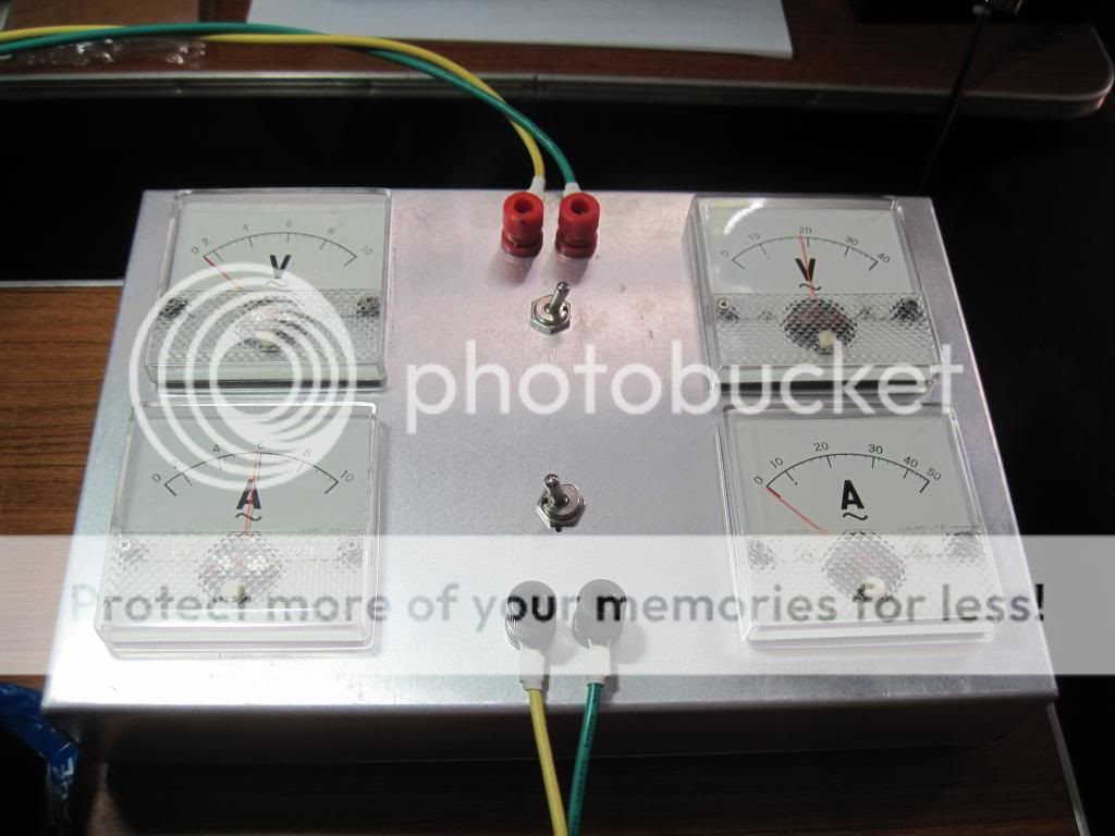
i attach a small spreadsheet showing copper losses at currents from 1 to 7amperes:
this is the traffo under test:
center leg of 2 inches stacked to 3 3/4 inch thick, core rating as per RDH4 is about 1750volt-amperes,
the traffo has since been finished with "poly-tuff" automotive filler and painted matte black.....
the purpose of this post is to demonstrate the open circuit(core loss) and short circuit(copper loss) testing of power traffo
to find out efficiencies under load, currents from 1A to 7A were used....
although core rating is 1750VA, i will rate this traffo as a 1200watt power traffo....
no load or open circuit testing using a kill-a-watt tester, in this test all secondaries of the traffo are left open...
no load current:
no load energy stored:
short circuit testing or copper loss test:
in this test all secondary winding's are joined together to form a short, a variac and my test contraption is used,
testing at several point from 1A to 7A....
i attach a small spreadsheet showing copper losses at currents from 1 to 7amperes:
Attachments
Last edited:
- Home
- Amplifiers
- Power Supplies
- Tony's latest traffo DIY build