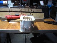
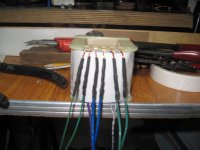
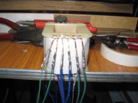
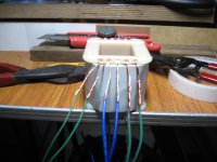
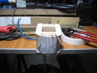
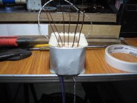
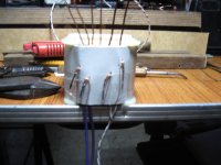
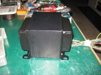
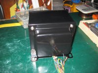
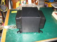
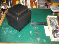
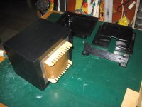
terminating pigtails on a power traffo...
Attachments
-
 IMG_5797.jpg408.2 KB · Views: 594
 -
 IMG_5808.jpg410.1 KB · Views: 186
 -
 IMG_5807.jpg381.9 KB · Views: 168
 -
 IMG_5806.jpg395.7 KB · Views: 157
 -
 IMG_5805.jpg404.9 KB · Views: 152
 -
 IMG_5804.jpg418.1 KB · Views: 158
 -
 IMG_5803.jpg445.2 KB · Views: 463
 -
 IMG_5802.jpg445.5 KB · Views: 488
 -
 IMG_5801.jpg408 KB · Views: 515
 -
 IMG_5800.jpg420.2 KB · Views: 573

AJT,
do you fit multiple Primary tappings to suit a range of supply voltages?
or
do you design the core/ampere turns to just not quite saturate when mains voltage is at it's highest?
How far do you allow the unloaded primary current to rise as your "limit" for acceptable non-saturation?
do you fit multiple Primary tappings to suit a range of supply voltages?
or
do you design the core/ampere turns to just not quite saturate when mains voltage is at it's highest?
How far do you allow the unloaded primary current to rise as your "limit" for acceptable non-saturation?
AJT,
do you fit multiple Primary tappings to suit a range of supply voltages?
or
do you design the core/ampere turns to just not quite saturate when mains voltage is at it's highest?
How far do you allow the unloaded primary current to rise as your "limit" for acceptable non-saturation?
i can do multiple primary tapping, when end users calls for it, but i find no use for it...
so i design for well below the knee of the saturation curves so that my traffos
do not saturate under any conditions of mains voltages or secondary loads...
regulation may not be be that good, but i will trade that for cool running traffos..
That's effectively what I do.i.................i design for well below the knee of the saturation curves so that my traffos
do not saturate under any conditions of mains voltages or secondary loads...
regulation may not be be that good, but i will trade that for cool running traffos..
measure and plot the primary current vs Vac curve and see how bad the standard 230Vac transformer is on our maximum of 253Vac. Then add on a dozen, or two dozen, primary turns and remeasure to check I have guessed about right.
That gets me cool running and higher efficiency when power demand is low.
Most transformers have average power demand well below 25% of maximum rated power.
Thanks for confirming.
Hi guys,
What are the various EI core material types I see specified. I've read in these pages about Mx or My related to different grades of steel used but it seems there's more than this. As an example I'd like to know what is meant by a specification such as
EI-212 X 3" 29GM6X
I'm guessing this is M6 material with a 3" tongue width.
Would appreciate a detailed breakdown on the rest or even better somewhere I can learn what all this data means.
Thanks
Martin
whoa...that is a big core you are looking at...what capacity in VA are you looking for?
if metric, 212mm/3 = 70mm or roughly 3nches, and the x 3" is the stacking height....
i saw laminations of this size in one of our local shops,
but to be honest i have yet to make a traffo that big for audio....
the biggest i have done is 2 1/4 x 5 1/2 inches and weighed in at 19kg, core only...
http://www.thomas-skinner.com/pdf/laminations_general.pdf
http://www.tempel.com/products/transformer/
EI-212 X 3"
if metric, 212mm/3 = 70mm or roughly 3nches, and the x 3" is the stacking height....
i saw laminations of this size in one of our local shops,
but to be honest i have yet to make a traffo that big for audio....
the biggest i have done is 2 1/4 x 5 1/2 inches and weighed in at 19kg, core only...
http://www.thomas-skinner.com/pdf/laminations_general.pdf
http://www.tempel.com/products/transformer/
Hi,
Ah, so the 212 is likely the metric width and the tongue is going to be 1/3 of that?
Total weight of the purchased version of this trafo is 29 LB so about 13kg, for what I'm interested in this is a baby heh heh. Secondary is specified as 1065VAC at 0.81A CCS. and there is a lower 780VAC available through an increased primary winding. So that's about 862VA @ CCS ratings though this actually feeds a diode doubler to run a pair of tubes at about 2.5kV and around 800mA at ICAS ratings.
This is not for an audio application to be honest but where else am I gonna find the best trafo info these days")
Links much appreciated, thanks.
Ah, so the 212 is likely the metric width and the tongue is going to be 1/3 of that?
Total weight of the purchased version of this trafo is 29 LB so about 13kg, for what I'm interested in this is a baby heh heh. Secondary is specified as 1065VAC at 0.81A CCS. and there is a lower 780VAC available through an increased primary winding. So that's about 862VA @ CCS ratings though this actually feeds a diode doubler to run a pair of tubes at about 2.5kV and around 800mA at ICAS ratings.
This is not for an audio application to be honest but where else am I gonna find the best trafo info these days
Links much appreciated, thanks.
Last edited:
Okay understood and thanks.
Regarding transformers where the coils are wound on the two outer legs rather than on the central tongue, and indeed where there is no central tongue. I recognise this is for insulation purposes generally for high secondary voltages but are there any adjustments to the way the transformer design is progressed or do all of the formula hold equally for both styles?
Regarding transformers where the coils are wound on the two outer legs rather than on the central tongue, and indeed where there is no central tongue. I recognise this is for insulation purposes generally for high secondary voltages but are there any adjustments to the way the transformer design is progressed or do all of the formula hold equally for both styles?
yes as far as formula goes, those could either be C cores or U-I cores....UI Core Supplier & Manufacturer from Kundla
Ok, good news. Hoping I can find the material I need in Bangkok. I recall seeing some shops with the right sort of stuff so hopefully they have what I'll need.
Going to start by adapting some old junk trafos for light duty use then progress to the bigger stuff.
This is what I'm working up to:

Going to start by adapting some old junk trafos for light duty use then progress to the bigger stuff.
This is what I'm working up to:
An externally hosted image should be here but it was not working when we last tested it.
I made some progress on my transformer musings. The big one I showed a picture of above seems to be okay. I had it running for a good few days with about 180v on the primary and seeing about 2500 on one half of the secondary. Next will be to test the chokes and the rectifier tube filament transformer. That will be on my next home trip.
I also did my first proper tear down of a normal EI core transformer. It went okay, a little tough pulling the first few E's but then it was fairly straight forward. The core that came out is almost totally epoxy encased the E is 1"7/8 x 4"1/4 stack so its quite a big core. I plan to rewind for about 2500v at 800mA, though not continuous duty.
On to my next question now I'm back at work where I can only really play with my audio amp projects. I'm putting together a stereo amp based on the Naim RCA layout. I have a RS comp 500VA toroid which is 30-0-30. Some experimentation shows this has about 0.3v per turn. I'm thinking to add a second 30-0-30 winding over the top to provide more of a dual mono arrangement. Is this feasible? It would need about 200 turns, around 40m of wire. Just wonder if I could do that by hand with a shuttle. Could be done in 2 goes with about 20m for each half.
Adding the same again is very likely to nearly fill the centre.
This will make it very difficult to feed through the last few dozen turns.
It hole may be too small for the "shuttle" to pass through.
That means passing a turn through and pulling the full remaining length without tangling with the other turn, which you are trying to pass around at the same time.
Alternatively you can do one winding, then the final winding will have a longer wire. What if you can't do the last couple of turns?
I had a tri-fillar 25Aac toroid. I opened it up to separate the three windings, added a fourth winding and then added 5Vac to each. This gave a 4 off 30Vac secondary . It was a tight squeeze to get the last few turns through and this was just adding 60% of copper. You are asking about adding 100% of copper.
Last edited:
I made some progress on my transformer musings. The big one I showed a picture of above seems to be okay. I had it running for a good few days with about 180v on the primary and seeing about 2500 on one half of the secondary. Next will be to test the chokes and the rectifier tube filament transformer. That will be on my next home trip.
I also did my first proper tear down of a normal EI core transformer. It went okay, a little tough pulling the first few E's but then it was fairly straight forward. The core that came out is almost totally epoxy encased the E is 1"7/8 x 4"1/4 stack so its quite a big core. I plan to rewind for about 2500v at 800mA, though not continuous duty.
On to my next question now I'm back at work where I can only really play with my audio amp projects. I'm putting together a stereo amp based on the Naim RCA layout. I have a RS comp 500VA toroid which is 30-0-30. Some experimentation shows this has about 0.3v per turn. I'm thinking to add a second 30-0-30 winding over the top to provide more of a dual mono arrangement. Is this feasible? It would need about 200 turns, around 40m of wire. Just wonder if I could do that by hand with a shuttle. Could be done in 2 goes with about 20m for each half.
if there is enough room to squeeze in the additional wires(i suspect there is) then by all means go ahead....
I think it might just work. The transformer is in situ now powering my Naim clone amp but once I get that sorted I'll probably add the extra winding and provide a dual mono supply. Thinking I might drop a wire size or two since overall current will be the same so the demands on the separated windings will be less.
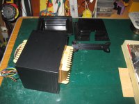
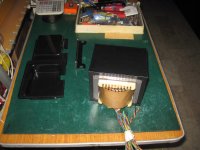
power traffo for 2016....1 3/4 x 4 inches, weight is about 12kg....
will be used in my upcoming 120Wpc 4D32 pp AB2 push-pull amp...
will be used in my upcoming 120Wpc 4D32 pp AB2 push-pull amp...
Attachments
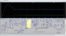
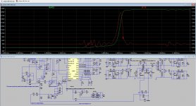
I go smps, busy now with a welder and later for my amps also, resonant bridges have sinusoidal resanonce with soft switching ans so no noise and such.
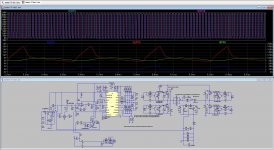
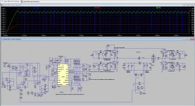
Picture two you see soft switch, red is cap on igbt and green is when it switch on while cap is charged by unload trafo, giving ZVS.
this examples are fase shift version.
And only as example that technologie of smps is really grown up.
Picture two you see soft switch, red is cap on igbt and green is when it switch on while cap is charged by unload trafo, giving ZVS.
this examples are fase shift version.
And only as example that technologie of smps is really grown up.
Attachments
Last edited:
- Home
- Amplifiers
- Power Supplies
- Tony's latest traffo DIY build