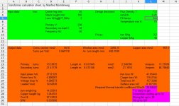
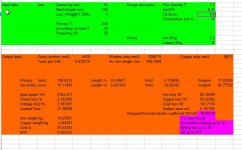
I have seen that the sheet for exel I did download do calculate a lot of possibilities of what is possible. Also it is said that flux density is important for how much I can get out, the laminels of my trafo are 0.5 mm thick and for welding I have read it is possible to use higher flux.
See picture of the calculations.
regards
kees
See picture of the calculations.
regards
kees
Attachments
Last edited:
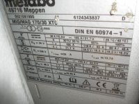
how hot was it running then?
If I did now I tell, I Have it from a scrapyard of how it is called in english.
I think I go for a inverter, I have the core,s, only I need a constant voltage source for Co2 welding with wire, I presume a smps with voltage feeback and current protection (above 130 amp it get in) is the way to go. electronics and pcb is no problem, however what chinese supplyer is to be trusted when order on ebay the IGBT,s and diodes.
I did see with current source inverter that only current is regulated and no voltage feedback make it open.
regards
kees
Thanks for the link.André
Not agree with this, read this paper.
Constant Current vs. Constant Voltage Output
Stick welding needs constant current source and MIG (wire feed) needs constant voltage (because of automatic feed of wire).
And so what to do with a inverter, have i build a normally power source with voltage feedback aca normal power supply and current protection.
The open voltage of my own MIG welder is 32 volts on max amps and has to be a voltage source the big coil in series with trafo act as the restistor to get this done.............
I see I have CC type welders for stick (oil cooled) and for TIG (air cooled).
Thanks for the link.
I see I have CC type welders for stick (oil cooled) and for TIG (air cooled).
yes onlt stick and tig, mig needs voltage source, wire is the current regulation factor (speed and volts) some has even a wire feed who speed control also affect the output voltage (professional stuff)..
I my case a choke in series with trafo do the trick.
regards
kees
I have calculate the trafo such that I have 140 amps on 21.2 volts like the welder has on manual, now it looks it fit and wire thickness etc is more normal.
I have use a flux of 1.35 T what is used for weld transformers.
program calculates load on output, so I think if i build the thing I get 32 volts open loop.
regards
kees
I have use a flux of 1.35 T what is used for weld transformers.
program calculates load on output, so I think if i build the thing I get 32 volts open loop.
regards
kees
Attachments
the problem as i see it is you do not know the actual quality of the irons you have in hand, you start winding a primary, then test for magnetising current and find out at what voltage your iron start to saturate, you will need a variac.....
i haven't done a welder before so i am also interested to know how yours will end up...
i haven't done a welder before so i am also interested to know how yours will end up...
try a flux density of 1.7T and you'll have much more reasonable results.
most stick welders have 80 volts open circuit.
With either adjustable magnetic shunts for current control or an inductor with multiple taps.
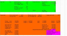
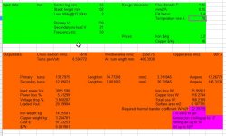
I did calculate it with flux 1.7T and a 0.35 mm2/A (was 0.5 normally but because of welding this is no problem, never continu duty).
This come in the naburehood, I get with this 85 amps and is x 1.8 153 amps, if I am right about it.
I do like the complete formula for the duty cylce because I am dutch it is more easely to read.
Oke with this I also need less copper.

And now the choke is left I have a core who is 3.8 x 5.1 cm is 38 x 51 mm = 1938 mm2, can I use this
for the max 150 amps with 30 windings, ? I do use the primairy with a
regards and thanks.
Last edited:
You can wind the primary, no secondary and test/measure the primary inductance using mains voltage as your test signal/frequency.
If you have a Variac, or a 230:100Vac transformer, you can wind approximately half the primary and test that to determine the final number of primary turns you need for the full 230/240/250Vac of the Mains supply.
Then it's easy to count on the number of turns for a fixed voltage secondary.
If you have a Variac, or a 230:100Vac transformer, you can wind approximately half the primary and test that to determine the final number of primary turns you need for the full 230/240/250Vac of the Mains supply.
Then it's easy to count on the number of turns for a fixed voltage secondary.
the problem as i see it is you do not know the actual quality of the irons you have in hand, you start winding a primary, then test for magnetising current and find out at what voltage your iron start to saturate, you will need a variac.....
i haven't done a welder before so i am also interested to know how yours will end up...
If for a spotwelder this trafo is also nice.
most go to 2000 amps but need secondairy wire 8 x 75 mm copper strip, not easy to wind, but it is just one winding.
But oke, this is not my problem now.
I have a 3 phase rectifier who has T7922-4 diodes on them, I can not find any stuff on google, Can I wind a single fase transformer such that I can do use this rectifier? otherwise I have remove two diodes. I can never reach 90 degree on a slinge fase transformer.
thanks.
Attachments
I did calculate it with flux 1.7T and a 0.35 mm2/A (was 0.5 normally but because of welding this is no problem, never continu duty).
This come in the naburehood, I get with this 85 amps and is x 1.8 153 amps, if I am right about it.
I do like the complete formula for the duty cylce because I am dutch it is more easely to read.
Oke with this I also need less copper.
And now the choke is left I have a core who is 3.8 x 5.1 cm is 38 x 51 mm = 1938 mm2, can I use this
for the max 150 amps with 30 windings, ? I do use the primairy with a
regards and thanks.
Attachments
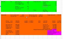
At last I have found a weld trafo company.
These says what to do.
just use T 1.35 for it, that is what she do and calculate power that way is pretty safe, but I think because it is a welder a T of 1.7 do also, but for a SCR on input I go lower and use the T 1.35 and then waiting what it does with unknown core EI core.
I did this before and now again, I go that way I think it is safe and make my bobine also more efficently used.
In the winter when I have more time I go make the inverter in stead and use this transformer for build spot welder.
regards
kees
Attachments
Can I wind a single fase transformer such that I can do use this rectifier? otherwise I have remove two diodes. I can never reach 90 degree on a slinge fase transformer.
sure you can....
can you show pics of your rectifier? you can use a 3 phase rectifier assembly using just the two ac inputs, no need to remove the other two, i have used 3 phase rectifiers like those before in ss audio amps like the one below...
An externally hosted image should be here but it was not working when we last tested it.
but for your needs, you want something much bigger...
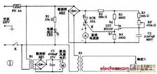
i see you want to vary the primary voltage, this is a neat circuit to use...
and the dc ammeter lets you monitor current...

For work on a car with thin metal this is nice to use. Chinese have somtimes good idea, I need a big rectifier there I gess, trafo is in serie with it.
the SCR of 10 amps, well, that is chinese, it blows.
The 3 fase rectifier is the same as you let see in the picture, only I have some cooling ribs on it, big ones.
I have seen that two diodes are not used, just uses it as a single fase rectifier,
regards
kees
My Dad, who worked for a communist company making phone relay switches for the Soviets built me a traffo like that in 1984. I ran a quad 405 clone with it, it was all decked out mil spec stuff...actually it was way nicer..and much bigger.1.9kw. And as I listen to the new Ncore 500, and other assorted class D all switched amps while my Threshold T50 and Classe CAM 350 collecting dust I ask...What the hell is going on here?
- Home
- Amplifiers
- Power Supplies
- Tony's latest traffo DIY build