Since you are considering an external power supply, your transformer need not be a toroid type, magnetic field is mitigated by the distance of the external PSU. It should be much easier to find a 12VAC transformer good for 2+ amps at low cost. One common source that comes to mind is outdoor garden lighting transformers, though they are usually higher current capacity than you would need for TA2020.
Use two of them with secondaries in series, where you join the secondaries is your center tap ground. Even though the two may be slightly different voltages it will work if you put regulators on positive and negative rails. It's just one idea, not necessarily the best one. You could also use two separate transformers, a tiny center tapped for the preamp and a larger for the TA2020, then you have no issue at all about power rail noise getting to the preamp, providing you use proper star grounding as with any amp.
How hard do you plan to push this amp? I powered a sonic T-amp with TA2024 (15W(?) version) at about 13.something volts and a moderate sized heatsink never gets excessively hot using LM317 to regulate. While I'm thinking about it, I threw it together quickly out of spare parts I had lying around and cannibalized part of an ancient computer router PCB and case to put it in, so it looks frankenstein ugly inside, but it gives you an idea how close I was able to put an E-core transformer without hearing any sound change, though just for the heck of it I put i a plain steel partition anyway.
I've used the amp in my garage over the past 5 years or so in (up to) 95F summer temperatures and it hasn't failed yet, though I usually only run it at about half volume so I don't annoy the neighbors.
An externally hosted image should be here but it was not working when we last tested it.
Hmm, the link isn't working for me, here it is:
http://img16.imageshack.us/img16/7563/sv300539.jpg
I'm sitting 30 cms from where the speakers (with the amp inside) will be. They will be on the table where i work every day. Next to a window that is open from spring to fall. And i have neighbors too
") So no, i won't push it i think.
So no, i won't push it i think. If i go the DIY psu way, i will use two transformers and two separate circuits. My only worry is: won't the final cable carrying 3 voltages from the psu to the amps be a very big antenna picking up noise? The preamp is opamp-based so it shouldn't be a problem (i believe i read somewhere they have very good power supply noise rejection)
Output of brick: 0 V and 24 V
Output of LM317 regulator: 0 V and 13.5 V
Feed to pre-amp: 0 V and 24 V from brick, with a virtual earth at 12 V to bias the pre amp
Feed to power amp: 0 V and 13.5 V from LM317
Signal from pre-amp to power amp: 0 V to 0 V and signal out to signal in via a capacitor.
So no problem with 0 V....
Possible problems that may, or may not, manifest:
- Power on thump due to DC offset, but power amp should have a mute delay.
- Ground loops, depending on layout and how solid the virtual earth on the pre-amp is
Try it, worse case you will learn something
PS. The LM317 should be mounted on a heat sink or metal sheet exposed to air from outside the wooden box. It will shut itself down before setting fire though.
I'm even more confused now. How would i achieve that? Would i have to create a virtual earth with an opamp like in this article?
You still have the problem of 0V.
Not so
The output from the DC/DC convertor is fully floating and isolated so you connect zero to wherever you want... in this case the 0 volts of the main PSU.
That gives 0-24vdc and -12/0/12 vdc.
Not so
The output from the DC/DC convertor is fully floating and isolated so you connect zero to wherever you want... in this case the 0 volts of the main PSU.
That gives 0-24vdc and -12/0/12 vdc.
That's what i thought!
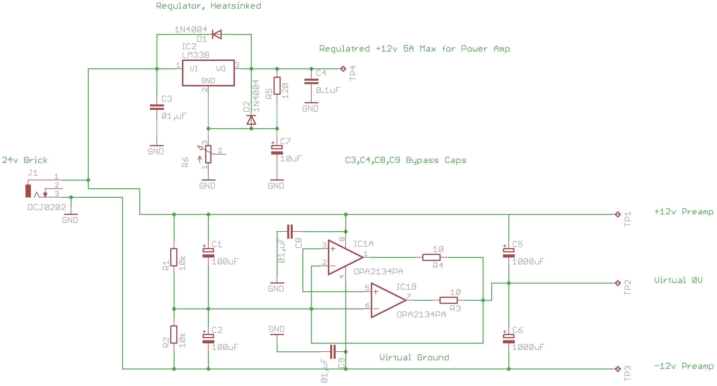
Ok so, i worked a bit on the schematic and i think much of the incomprehension came from my poor skills rather than actual problems, i apologize for that.
To draw this schematic i copied information from:
- LM338 Datasheet for the single rail +12v part
- Rod Elliot's Project 43 - Ultra Simple Split DC Supply For the dual rail part of the schematic.
- I added bypass caps everywhere was suggested to but not shown in the schematic, that would be Ceramic Discs 0.1uF: C3 and C4 on the LM338 Regulator, and C8 and C9 on the supply pin of the opamp
So here is it, what did i get wrong this time?
Thanks for your feedback!
I'm even more confused now. How would i achieve that? Would i have to create a virtual earth with an opamp like in this article?
It is the same idea as the ESP article you quoted in the beginning.
The wiki article you linked has a good link as well:
Virtual Ground Circuits
It is the same idea as the ESP article you quoted in the beginning.
The wiki article you linked has a good link as well:
Virtual Ground Circuits
I believe my second schematic is correct according to Rod Elliot's site?
Like this. Now your virtual earth point can be connected to ground giving a true -/+ supply.
Wait. The dc/dc converter you linked has an input voltage of +12v and can output a +/-12v? But then i don't need 24v anymore.
I only used 24v in the beginning because rod elliot's split supply used 24v to obtain +/-12v. My laptop brick has selectable output, i can very well just buy that dc/dc converter and use +12v straight from the power brick!
I could then have the poweramp fed directly from the dc jack (maybe with *minor* regulation, requiring no heatsink), and use the dc/dc converter to have a *real* dual power supply!
Is this correct? am i understanding this correctly?
That's what i thought!
Ok so, i worked a bit on the schematic and i think much of the incomprehension came from my poor skills rather than actual problems, i apologize for that.
To draw this schematic i copied information from:
- LM338 Datasheet for the single rail +12v part
- Rod Elliot's Project 43 - Ultra Simple Split DC Supply For the dual rail part of the schematic.
- I added bypass caps everywhere was suggested to but not shown in the schematic, that would be Ceramic Discs 0.1uF: C3 and C4 on the LM338 Regulator, and C8 and C9 on the supply pin of the opamp
So here is it, what did i get wrong this time?
Thanks for your feedback!
Just don't connect Virtual 0V to 0V because they are different DC potentials.
Just don't connect Virtual 0V to 0V because they are different DC potentials.
Its not that easy as both are used as reference points for the audio... they have to be connected. Can't think of an easy way to explain it
That's what i thought!
So here is it, what did i get wrong this time?
Thanks for your feedback!
As said before, it will work if you AC couple the pre-amp and power amp.
(Just fix the small error: R1/R2 junction should tie to the +IN, not -IN, of the opmps).
But if your brick can do +12V, the DC-DC convertor solution of Mooly is much more elegant.
If you can get a 12v AC transformer you can use a Voltage doubler and regulators to get your +/- 12v DC then use a seperate rectifier and regulator for your 12v DC for the power amp ......
The Preamp won"t use very much current so a voltage doubler would be suitable and there isn"t a problem with it sucking more from one rail .....
Cheers
The Preamp won"t use very much current so a voltage doubler would be suitable and there isn"t a problem with it sucking more from one rail .....
Cheers
I'll fix the schematic as soon as possible, but i think i'll go with Mooly's solution. Would it be a good idea to regulate the 2 rails after the dc/dc converter as well? or would that be overkill?
Best regards,
GC
You have many options... you could go with a 15/0/15 convertor and use 78and 79L12 regs. The 3 volts is sufficient headroom for these to work well.
You could just use a simple R/C filter feeding the opamp rails.
Or just use it "as is" with suitable caps on each rail.
Or again with a 15 volt reg you could use a resistor/zener/cap arrangement which in many cases for low currents is a very good option... this "shunt" arrangement is the one I use in my integrated amp.
Do we need to filter the split rail that we are achieving from the DC/DC converter, as both this and the main PSU are switching power supplies?
and switching power suppliers are known to be noisy especially for audio pre amplifiers.
Do we need to look for additional high bandwidth PSSR LDO after DC/DC rail splitter or a pi CLC filter or any other filtering ?
thanks and regards
S Sarath
- Status
- This old topic is closed. If you want to reopen this topic, contact a moderator using the "Report Post" button.
- Home
- Amplifiers
- Power Supplies
- Single 12v and +-12v needed, What options?