Hi, i'm currently working on a very space constrained project and i'm in need of a single 12v supply line for a power amp (a Arjen Helder ta2020 module from ebay) and a +-12v for a preamp.
The whole thing is tightly constrained inside a small speaker cabinet (this is gonna be a set of active speakers for a desktop) so at the moment i picked an external laptop power supply (24v) and used the schematic of Rod Elliot's Split DC Power supply to get the relevant +-12v for the pre.
From the same power input, i need to get straight 12v for the power amp but i can't tap the +12v from the dual as it would create a very strong current imbalance and that's not really advisable as i understand.
At the moment i'm thinking of using a LM7812 but i don't know how much current will flow through the regulator.
How much would the ta2020 absorb in a standard setting? Speakers are 5w rating and they are 8ohm, so the *sound* power the amp will put out is around 12w.
Is the 7812 a valid solution or i'm risking setting something on fire?
here's a rough schematic of how the whole thing is going to work
Thanks for your input
Last edited:
That circuit will DEFINITELY NOT WORK
As drawn the output of the 7812 will be +24V (or close to it). The 0V of the 7812 will be floating as it is not tied to a HARD GROUND.
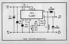
Best bet would be to use 2 x 7812s one for pre +12V and one for power +12V. Then build a simple invertor using the TL497 (simple applications are shown in the datasheet.
As drawn the output of the 7812 will be +24V (or close to it). The 0V of the 7812 will be floating as it is not tied to a HARD GROUND.
Best bet would be to use 2 x 7812s one for pre +12V and one for power +12V. Then build a simple invertor using the TL497 (simple applications are shown in the datasheet.
Attachments
Last edited:
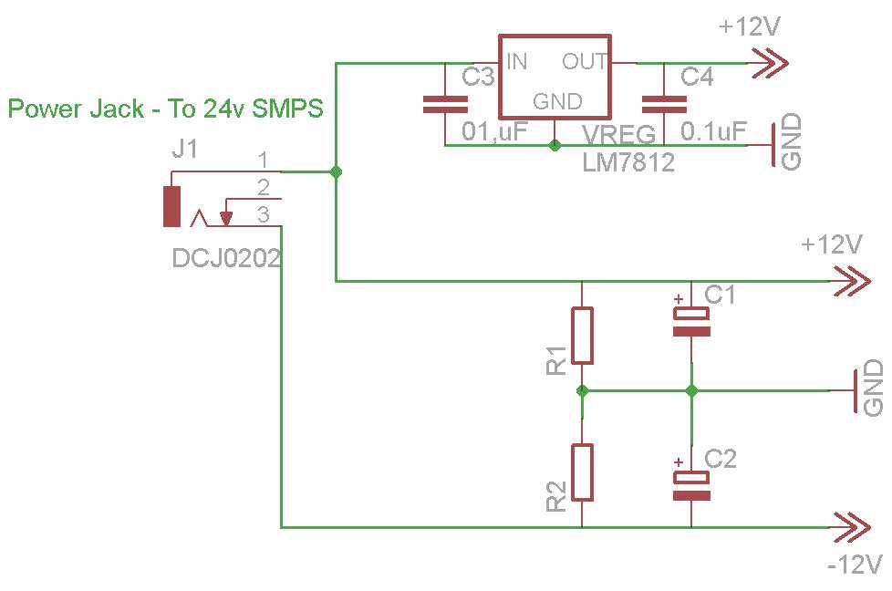
As it's already obvious, i'm a newbie but i don't understand why the output of the regulator should be 24v, it was a very quick sketch but what i meant is :
The capacitors are mentioned in the datasheet of the regulator as useful for eliminating transients and they are connected between each pin and ground, as instructed in the datasheet (in one of the demo circuit illustrations).
If it's not too much bother could you please tell me what's wrong in the above? Thank you very much for your input.
- Feed 24v to the regulator, with the + on the input of the regulator
- Ground to the ground of the regulator
- As i understand, the output pin of the regulator should have +12v?
The capacitors are mentioned in the datasheet of the regulator as useful for eliminating transients and they are connected between each pin and ground, as instructed in the datasheet (in one of the demo circuit illustrations).
If it's not too much bother could you please tell me what's wrong in the above? Thank you very much for your input.
The +/- 12V circuit you have drawn only works with very low and equal currents being drawn from both sides + & -.
If you connect the 0V of the regulator to the 0V of the +/- circuit, regulator will try to use the -ve supply as its return path.
The +/- will no longer be +/- 12V and the 7812 will kick out 12V above whatever it is seeing on its 0V terminal.
Under no-load it would appear OK but as soon as you try to draw any current the voltages will all go to s**t.
Also you have the problem that the amps 0V is not at the same potential as the pre-amps 0V.
I see. Well i have a DC power jack coming from the laptop brick.
I was planning on running 1 ground and 1+ from the jack for the +/- board and 1 ground and 1+ for the lm7812 board.
Shouldn't the 0V of the LM7812 refer to the 0V of the laptop brick that way?
Also, the +/v part will use an opamp to fix the current imbalance, and it's meant for a pre so current should be enough (i'm following Rod Elliot's recommendations and the target preamp is P88 from his website).
Thank you very much again for your support")
PS: Well i'm really open to suggestions, i just need a dual power supply for the pre and a single-ended one for the power amp. Any solution that can fit on a 60x60mm (maybe a little more) breadboard and that i can possibly build myself is welcome.
I was planning on running 1 ground and 1+ from the jack for the +/- board and 1 ground and 1+ for the lm7812 board.
Shouldn't the 0V of the LM7812 refer to the 0V of the laptop brick that way?
Also, the +/v part will use an opamp to fix the current imbalance, and it's meant for a pre so current should be enough (i'm following Rod Elliot's recommendations and the target preamp is P88 from his website).
Thank you very much again for your support
PS: Well i'm really open to suggestions, i just need a dual power supply for the pre and a single-ended one for the power amp. Any solution that can fit on a 60x60mm (maybe a little more) breadboard and that i can possibly build myself is welcome.
Last edited:
How would that solve the problem? I'd still have a dual power supply with one rail draining much more current than the other. As far as i know that is really bad?
Its not a problem at all.
Best bet is to build your own SMPS. Not a 240V one as they are very difficult to build, but one that runs from your 24V plug-in.
I'll draw up an idea and post it in half an hour or so.
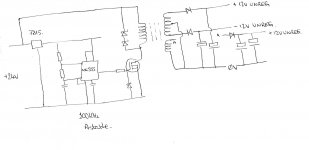
Just to give you a rough idea.
Use a basic NE555 running in Astable (Oscillator) mode to drive a MOS-FET.
The Drain Load on the MOS-FET is a simple ferrite transformer.
The secondaries of the ferrite can be constructed to give you your +/- 12V and +12V secondaries.
If the load is constant you shouldn't need any regulators except the 15V reg for the NE555.
With a bit of practice low voltage SMPS designs are easy to build.
I'll draw up an idea and post it in half an hour or so.
Just to give you a rough idea.
Use a basic NE555 running in Astable (Oscillator) mode to drive a MOS-FET.
The Drain Load on the MOS-FET is a simple ferrite transformer.
The secondaries of the ferrite can be constructed to give you your +/- 12V and +12V secondaries.
If the load is constant you shouldn't need any regulators except the 15V reg for the NE555.
With a bit of practice low voltage SMPS designs are easy to build.
Attachments
Last edited:
How much would the ta2020 absorb in a standard setting? Speakers are 5w rating and they are 8ohm, so the *sound* power the amp will put out is around 12w.
t
According to the data sheet for13.5 V supply into 8 ohm, maximum power will be 10 W with 10%! THDN or 7 W with 0.1% THDN.
Regulate the 24 V laptop brick down to 13.5 V for the power amp. You can use an LM317, LM7815, etc. for this. LM338 would be better (5 A instead of 1.5 A capacity). You will need a heat sink for the regulator.
Run the pre from your virtual split supply as planned.
AC-couple the pre output to the power amp input using an MKP or MKT capacitor, 1 to 10 uF, depending on the input impedance of the amp. The pre output, power amp input, or both, may even already be AC coupled....
How would that solve the problem? I'd still have a dual power supply with one rail draining much more current than the other. As far as i know that is really bad?
Not a problem.
If transformer is rated at full current of power amp then the reduced current on the -ve pre-amp leg is easy meat for it.
These are a good option if space is tight and current requirements modest,
Your Search Results | CPC
Or a 15 volts one that allows you to add further regulation if you want,
Your Search Results | CPC
Your Search Results | CPC
Or a 15 volts one that allows you to add further regulation if you want,
Your Search Results | CPC
I appreciate everybody's feedback immensely. Thanks to andy5112405 for the SMPS idea, i will definitely steal it sooner rather than later but running my own switching supply is a bit past my possibilities at the moment.
This is what i meant to do from the start. My original question was if stepping down from 24v to over 10v lower would mean having HAZARDOUS amounts of heat in a wooden cabinet. I take your answer as a no?
i will proceed with this way then, if the heat issue is confirmed as non-existant. I will use the 5A version with a sizable heatsink and see from there. I'll try to sketch something up soon and maybe i can abuse everybody's kindness again
EDIT: Also, it seems clipping won't be a problem given the speakers will be Fostex FE83, which are rated for 5W. So hopefully i will never hit the 7w treshold ^^
According to the data sheet for13.5 V supply into 8 ohm, maximum power will be 10 W with 10%! THDN or 7 W with 0.1% THDN.
Regulate the 24 V laptop brick down to 13.5 V for the power amp. You can use an LM317, LM7815, etc. for this. LM338 would be better (5 A instead of 1.5 A capacity). You will need a heat sink for the regulator.
Run the pre from your virtual split supply as planned.
AC-couple the pre output to the power amp input using an MKP or MKT capacitor, 1 to 10 uF, depending on the input impedance of the amp. The pre output, power amp input, or both, may even already be AC coupled....
This is what i meant to do from the start. My original question was if stepping down from 24v to over 10v lower would mean having HAZARDOUS amounts of heat in a wooden cabinet. I take your answer as a no?
i will proceed with this way then, if the heat issue is confirmed as non-existant. I will use the 5A version with a sizable heatsink and see from there. I'll try to sketch something up soon and maybe i can abuse everybody's kindness again
EDIT: Also, it seems clipping won't be a problem given the speakers will be Fostex FE83, which are rated for 5W. So hopefully i will never hit the 7w treshold ^^
Last edited:
These are a good option if space is tight and current requirements modest,
Your Search Results | CPC
Or a 15 volts one that allows you to add further regulation if you want,
Your Search Results | CPC
The input voltage appears to be too low (~5v for the first, ~10v for the second) as i'm dealing with 24v. But i'll save this for future reference, thanks!
I don't understand how it works sadly :/.
I can't have two circuits from the same power supply? How do PC power supplies work then? with dozes of different voltages? Among all the solutions suggested here (of which i'm thankful for), the only one that i canget my head around to is discrete's one.
I don't have the expertise to run my own SMPS from scratch and the trial and error would take months :/ and i can't run a transformer inside a 20x20cmx30 cabinet together with damping material, a speaker cone and 4 circuit boards.
Isn't there a way to supply the regulator a real 0V?
Last edited:
I honestly didn't foresee this many complications in something i chose exactly because it was a quicker solution (using a laptop brick instead of building a supply from scratch).
How much do you think it would cost to build a supply of my own? At this point i'm open to suggestions, provided the cost is not prohibitive. Last time i checked, transformers were very expensive (30-40euros for a toroidal of a few tens of VAs).
The choice of the laptop brick was inspired by
But as it's turning out now, there is loads of added complexity, and i'm actually not saving that much room anymore. So i might as well consider other options.
I can't spend more than 50-60euros for the whole supply, from AC Mains to final supply lines (+12 for the power amp, +/-12 for the pre).
I'm very appreciative of all the hassle you are all going through to help with this problem If it's of any help, i'll be sure to post a detailed build log once i'm through (not sure if that's welcome around here?)
How much do you think it would cost to build a supply of my own? At this point i'm open to suggestions, provided the cost is not prohibitive. Last time i checked, transformers were very expensive (30-40euros for a toroidal of a few tens of VAs).
The choice of the laptop brick was inspired by
- External Power Supply (for space reasons)
- Lots of power on the cheap (120w for 30-35 euros)
- Reduced complexity.
But as it's turning out now, there is loads of added complexity, and i'm actually not saving that much room anymore. So i might as well consider other options.
I can't spend more than 50-60euros for the whole supply, from AC Mains to final supply lines (+12 for the power amp, +/-12 for the pre).
I'm very appreciative of all the hassle you are all going through to help with this problem
If it's of any help, i'll be sure to post a detailed build log once i'm through (not sure if that's welcome around here?)
Last edited:
Since you are considering an external power supply, your transformer need not be a toroid type, magnetic field is mitigated by the distance of the external PSU. It should be much easier to find a 12VAC transformer good for 2+ amps at low cost. One common source that comes to mind is outdoor garden lighting transformers, though they are usually higher current capacity than you would need for TA2020.
Use two of them with secondaries in series, where you join the secondaries is your center tap ground. Even though the two may be slightly different voltages it will work if you put regulators on positive and negative rails. It's just one idea, not necessarily the best one. You could also use two separate transformers, a tiny center tapped for the preamp and a larger for the TA2020, then you have no issue at all about power rail noise getting to the preamp, providing you use proper star grounding as with any amp.
How hard do you plan to push this amp? I powered a sonic T-amp with TA2024 (15W(?) version) at about 13.something volts and a moderate sized heatsink never gets excessively hot using LM317 to regulate. While I'm thinking about it, I threw it together quickly out of spare parts I had lying around and cannibalized part of an ancient computer router PCB and case to put it in, so it looks frankenstein ugly inside, but it gives you an idea how close I was able to put an E-core transformer without hearing any sound change, though just for the heck of it I put i a plain steel partition anyway.
I've used the amp in my garage over the past 5 years or so in (up to) 95F summer temperatures and it hasn't failed yet, though I usually only run it at about half volume so I don't annoy the neighbors.
Hmm, the link isn't working for me, here it is:
http://img16.imageshack.us/img16/7563/sv300539.jpg
Use two of them with secondaries in series, where you join the secondaries is your center tap ground. Even though the two may be slightly different voltages it will work if you put regulators on positive and negative rails. It's just one idea, not necessarily the best one. You could also use two separate transformers, a tiny center tapped for the preamp and a larger for the TA2020, then you have no issue at all about power rail noise getting to the preamp, providing you use proper star grounding as with any amp.
How hard do you plan to push this amp? I powered a sonic T-amp with TA2024 (15W(?) version) at about 13.something volts and a moderate sized heatsink never gets excessively hot using LM317 to regulate. While I'm thinking about it, I threw it together quickly out of spare parts I had lying around and cannibalized part of an ancient computer router PCB and case to put it in, so it looks frankenstein ugly inside, but it gives you an idea how close I was able to put an E-core transformer without hearing any sound change, though just for the heck of it I put i a plain steel partition anyway.
I've used the amp in my garage over the past 5 years or so in (up to) 95F summer temperatures and it hasn't failed yet, though I usually only run it at about half volume so I don't annoy the neighbors.
An externally hosted image should be here but it was not working when we last tested it.
Hmm, the link isn't working for me, here it is:
http://img16.imageshack.us/img16/7563/sv300539.jpg
Last edited:
You still have the problem of 0V.
Output of brick: 0 V and 24 V
Output of LM317 regulator: 0 V and 13.5 V
Feed to pre-amp: 0 V and 24 V from brick, with a virtual earth at 12 V to bias the pre amp
Feed to power amp: 0 V and 13.5 V from LM317
Signal from pre-amp to power amp: 0 V to 0 V and signal out to signal in via a capacitor.
So no problem with 0 V....
Possible problems that may, or may not, manifest:
- Power on thump due to DC offset, but power amp should have a mute delay.
- Ground loops, depending on layout and how solid the virtual earth on the pre-amp is
Try it, worse case you will learn something
PS. The LM317 should be mounted on a heat sink or metal sheet exposed to air from outside the wooden box. It will shut itself down before setting fire though.
- Status
- This old topic is closed. If you want to reopen this topic, contact a moderator using the "Report Post" button.
- Home
- Amplifiers
- Power Supplies
- Single 12v and +-12v needed, What options?