This isn't as easy as it appears especially at 100Khz operation in hard switching continuous mode.The inductor has been optimised for Vin min at 265V and the current limit at this figure is correct, an easy implementation with the ST L4981A with an external driver. Inductor is E42 core 2mm gap.
The problem is choosing the correct switching device..
Sadly, the 600V output voltage deletes using raft of fast diodes in this range; I have been using the 1000V STTH1210D fast recovery diode but at 600V, I would prefer remaining with an IGBT......and it appears very few are suitable at this operating frequency.
Someone in another site suggested an 800V 17A Coolmos which I tried but this ended up in a big bang, so it appears these devices aren't suited for hard pfc. Despite an RF type layout, I suspect the cross capacitance within the device is the cause of the problem or Can anyone give another explanation ?
Anyone suggest a device ?
richy
Yes I have (many thanks)....however I would have to redesign my long standing 500V version which uses 600V devices which I want to use. It appears the To247 version SKW25N120 fast igbt could fit the bill......at a price.
I strongly suspect the culprit is also the slowish current limit performance of the L4981A....a quick look at the Tekt screen does show some sneak transient high current spikes exactly at the point when forced current limiting occurs despite Ipk calculated well within margins. With my lower voltage pfc version I never had a single issue using IGBT's esp HGTP12N60A4 with this IC.
richy
I rather like IGBT's for HV off line apps.
I've found the problem that my son had, he is using an E42/20 core 1mH 1.5mm gap; 100Khz, below 18% ripple current, worked out with the ST pfc software program..this is fine to 700W (just)..However the peak current bug appears when the min AC input is dropped below the calculations, and then internal current limiting should limit ton/duty cycle to avoid core problems...which in this case it didn't and destroyed both switch and rectifier. Proper current limit tailoring is vital for proper duty cycle current limited operation of the power stage.
A coolmos high current very low RDS type isn't the ideal for this circuit.
He was correct in reducing the Iripple in tackling the common and diff mode interference issues to acceptable levels, but the point is not all software programs are 100% correct.
It pays to keep to conventional type mosfets and an ultra fast diode as suggested in the app note.
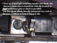
The layout of the power stage is instrumental for reliable operation and keeping the overshoot down. Note shortest possible connections and the diode cathode tab (not seen) directly connected to the top pcb side and connected to the output caps for the lowest inductance.
600V output at 100Khz reduced to 600W is quite feasible with an RF approach, double sided PCB and plenty of ground vias.
Happy ending.
richy
A coolmos high current very low RDS type isn't the ideal for this circuit.
He was correct in reducing the Iripple in tackling the common and diff mode interference issues to acceptable levels, but the point is not all software programs are 100% correct.
It pays to keep to conventional type mosfets and an ultra fast diode as suggested in the app note.
The layout of the power stage is instrumental for reliable operation and keeping the overshoot down. Note shortest possible connections and the diode cathode tab (not seen) directly connected to the top pcb side and connected to the output caps for the lowest inductance.
600V output at 100Khz reduced to 600W is quite feasible with an RF approach, double sided PCB and plenty of ground vias.
Happy ending.
richy
Attachments
- Status
- This old topic is closed. If you want to reopen this topic, contact a moderator using the "Report Post" button.