Snubber for center tap
Do you think that this is the right way of implementing a snubber network for a full wave rectifier using a secondary with centre tap? I am referring to Hagerman's article as far as "calculated" is concerned:

And I say one diode because he mentions that for a bridge rectifier, we should take into consideration two diodes in series, so half the diode capacitance in the equations.
Is there a way of installing only one snubber between across the whole secondary?
Thanks in advance.
Do you think that this is the right way of implementing a snubber network for a full wave rectifier using a secondary with centre tap? I am referring to Hagerman's article as far as "calculated" is concerned:
And I say one diode because he mentions that for a bridge rectifier, we should take into consideration two diodes in series, so half the diode capacitance in the equations.
Is there a way of installing only one snubber between across the whole secondary?
Thanks in advance.
As the two halves of the secondary are fairly strongly coupled together I would use only one snubber. Remember, many circuits work quite happily with no snubber so perfection is not required.
While I have never seen any evidence that diodes need snubbering, the snubber should be placed close to the device being snubbered, try simulating it and then put a load of stray inductance in series with the snubber and observe what happens to the snubbering action.
Same goes for the assertion the the two halves of the secondary are closely coupled, at frequencies close to the transformer design frequency the coupling is strong, coupling falls off with frequency, then stray inductance and capacitance play all sorts of games.
Even a well designed audio output transformer has trouble maintaining good coupling over 3 decades of frequency, the design frequency for the snubber mentioned here is 4 decades above the transformer design frequency.
Thanks for your replies.
I am mainly asking since I will order the transformer, and I don't already have an estimate of the winding capacitance. Should it be low, the individual diode capacitance could matter more, even though as you say (DF96) we don't have to get mad about perfection - I agree on that.
So, for two snubbers, I calculate one diode for each, and for one across the whole secondary, I calculate two? Curious about what gets into the math.
Just to avoid any confusion, we need to distinguish between transformer snubbering and diode snubbering. I assume that post 21 was about transformer snubbering.
Transformer snubbering is about what happens when the diodes switch off 'normally' - the issue is stored magnetic energy. A fairly low frequency issue.
Diode snubbering is about what happens when the diodes switch off 'suddenly' (i.e. with stored charge). A fairly high frequency issue.
In addition, in equipment containing RF oscillators there is the separate issue of modulation hum.
In a switching power supply one would normally place a series RC in parallel with each diode, if a snubber is used. I can't see a real benefit from placing it across the winding.
Personally I do not see the purpose of a snubber at line frequency. If your diodes are that noisy, you've used the wrong diode. There's nothing wrong with good ol' slow general purpose diodes here.
Personally I do not see the purpose of a snubber at line frequency. If your diodes are that noisy, you've used the wrong diode. There's nothing wrong with good ol' slow general purpose diodes here.
Well I am actually referring to Hagerman's article - so, I mean diode snubbering, to kill the oscillation while switching off.
I have not built it yet, I am planning to do so. Which means I am designing it on the first place - should I ever need snubbering, I would like to know how to get it. And since I will use a toroidal transformer, I may get weird readings compared to the article, so I must really know what I am doing.")
I have not built it yet, I am planning to do so. Which means I am designing it on the first place - should I ever need snubbering, I would like to know how to get it. And since I will use a toroidal transformer, I may get weird readings compared to the article, so I must really know what I am doing.
To damp any overshoot, from diode turnoff delay the snubber should be in parallel with the diode(s) being snubbered, using short leads. Leads introduce series inductance which reduces the effectiveness of snubbers and provides a means to radiate the energy that the snubber is designed to absorb. This is general advice which applies to all RC snubber circuits.
To damp any overshoot, from diode turnoff delay the snubber should be in parallel with the diode(s) being snubbered, using short leads. Leads introduce series inductance which reduces the effectiveness of snubbers and provides a means to radiate the energy that the snubber is designed to absorb. This is general advice which applies to all RC snubber circuits.
Could we say that this is what equally Hagerman does, placing it across the secondary? In terms of thinking that the reservoir capacitor will appear to be a short circuit during the high frequency oscillation, and will somewhat connect the diode to the snubber?
I may just be wrong.
The reservoir capacitor will appear as a low impedance to any high frequency, The transformer will appear as a high impedance so most of the high frequency will appear across the transformer. What you choose to do about this depends on what you are trying to achieve. Placing a snubber across the transformer secondary will reduce the amount of high frequency that the transformer sees. Hagerman may have had a reason to reduce the high frequency the power transformer might see. Placing a snubber in parallel with the diodes will keep any high frequency local to the diodes.
Some interesting findings, now that I found some time to work with PSpice.
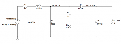
I simulated the exact circuit that Hagerman did, using the same model he used for the 1N4007. To cut the story short, this is the circuit I used:

So, firstly, I specified the diode's recovery time as 7.2us. This is what I got at the point where I put the probe:

After that, I left the 1N4007 PSpice model the same, except for changing the recovery time to 750ns (making it shorter). The result:

And, up to 75ns:

75ns is the typical value of a UF4007 diode, according to datasheets. So, this gives credit to anyone that just pays for some better diodes and does not bother with snubbers.
Anyway, these are simulation findings - what remains to be seen, is whether we can also get experimental evidence of these facts.
I simulated the exact circuit that Hagerman did, using the same model he used for the 1N4007. To cut the story short, this is the circuit I used:
So, firstly, I specified the diode's recovery time as 7.2us. This is what I got at the point where I put the probe:
After that, I left the 1N4007 PSpice model the same, except for changing the recovery time to 750ns (making it shorter). The result:
And, up to 75ns:
75ns is the typical value of a UF4007 diode, according to datasheets. So, this gives credit to anyone that just pays for some better diodes and does not bother with snubbers.
Anyway, these are simulation findings - what remains to be seen, is whether we can also get experimental evidence of these facts.
I simulated the exact circuit that Hagerman did
If you want to see the LC circuit's oscillatory ringing, you've got to give it a stimulus. The standard analogy is a bell: you've got to smack the bell with a mallet, to make it ring.
In this case, (L = transformer secondary leakage inductance), (C= transformer secondary capacitance + rectifier capacitance), and the stimulus is a large dI/dt. To get a large dI/dt, increase the filter capacitance to narrow the current pulse, and decrease the load resistance to make the current pulse taller. Voila, large dI/dt.
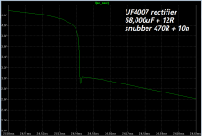
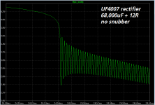
I simulated this in LTSPICE using the Vishay Semiconductor Ultrafast rectifier "UF4007" spice model, schematic below. As you can see, I was able to get oscillatory ringing. Also as you can see, Hagerman's proposed snubber resistance (470 ohms) damped the ringing perfectly.
Conclusion: Un-snubbed transformer secondaries CAN oscillate, even with UltraFast rectifiers.
.
.
Attachments
If you want to see the LC circuit's oscillatory ringing, you've got to give it a stimulus. The standard analogy is a bell: you've got to smack the bell with a mallet, to make it ring.
In this case, (L = transformer secondary leakage inductance), (C= transformer secondary capacitance + rectifier capacitance), and the stimulus is a large dI/dt. To get a large dI/dt, increase the filter capacitance to narrow the current pulse, and decrease the load resistance to make the current pulse taller. Voila, large dI/dt.
I simulated this in LTSPICE using the Vishay Semiconductor Ultrafast rectifier "UF4007" spice model, schematic below. As you can see, I was able to get oscillatory ringing. Also as you can see, Hagerman's proposed snubber resistance (470 ohms) damped the ringing perfectly.
Conclusion: Un-snubbed transformer secondaries CAN oscillate, even with UltraFast rectifiers.
.
.
Hmmm. Sounds like another plus for choke input supplies. Much lower dI/dt, so they are less likely to induce ringing.
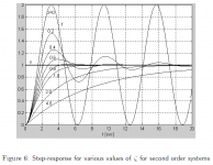
Member I_will_run_spice_for_you might volunteer to perform that simulation, or you could run it yourself. A third option, and the one that I prefer myself, is to agree with Hagerman that this is a classical second order system with damping factor Zeta (wikipedia). Then all you need to do is calculate the Zeta of the parallel RLC circuit, whose R=330, L=1.33E-4, C=5.5E-10.
It's the 2nd boxed equation on Hagerman's page 4:
which yields, after rearrangement, Zeta = (1/(2*Rsnub))*sqrt(L/C) . Plugging in the numbers for this particular transformer & rectifier, we get Zeta ~ 0.73 . Would a waveform with damping factor 0.73 please you?
It's the 2nd boxed equation on Hagerman's page 4:
- Rsnub = (1/(2*Zeta))*sqrt(L/C)
which yields, after rearrangement, Zeta = (1/(2*Rsnub))*sqrt(L/C) . Plugging in the numbers for this particular transformer & rectifier, we get Zeta ~ 0.73 . Would a waveform with damping factor 0.73 please you?
Attachments
Member I_will_run_spice_for_you might volunteer to perform that simulation, or you could run it yourself. A third option, and the one that I prefer myself, is to agree with Hagerman that this is a classical second order system with damping factor Zeta (wikipedia). Then all you need to do is calculate the Zeta of the parallel RLC circuit, whose R=330, L=1.33E-4, C=5.5E-10.
It's the 2nd boxed equation on Hagerman's page 4:
- Rsnub = (1/(2*Zeta))*sqrt(L/C)
which yields, after rearrangement, Zeta = (1/(2*Rsnub))*sqrt(L/C) . Plugging in the numbers for this particular transformer & rectifier, we get Zeta ~ 0.73 . Would a waveform with damping factor 0.73 please you?
Thanks for nothing.
I am perfectly capable of running a spice sim, but being on the road and not having my computer with me I thought you could plug the numbers into the sim you've already run.
Forget it. Happy Easter.
If you want to see the LC circuit's oscillatory ringing, you've got to give it a stimulus. The standard analogy is a bell: you've got to smack the bell with a mallet, to make it ring.
In this case, (L = transformer secondary leakage inductance), (C= transformer secondary capacitance + rectifier capacitance), and the stimulus is a large dI/dt. To get a large dI/dt, increase the filter capacitance to narrow the current pulse, and decrease the load resistance to make the current pulse taller. Voila, large dI/dt.
I simulated this in LTSPICE using the Vishay Semiconductor Ultrafast rectifier "UF4007" spice model, schematic below. As you can see, I was able to get oscillatory ringing. Also as you can see, Hagerman's proposed snubber resistance (470 ohms) damped the ringing perfectly.
Conclusion: Un-snubbed transformer secondaries CAN oscillate, even with UltraFast rectifiers.
.
.
I could not agree more. Still, please observe my point: I said that better diodes can ameliorate the situation, not extinguish the problem completely. Sorry if I did not make that clear.
But what your simulation does show to me, is that for relatively normal load requirements, a good diode could eliminate unwanted interference. Given the numbers for leakage and parasitic capacitance are logical, of course.
For example, I am planning to build a bridge with an input cap of 4700u, giving roughly 200mA at 14-15V - a 76 ohm load. Seems like a UF4002 could be sufficient for this.
I just wanted to make this clear - to myself, too - since leakage and stray capacitance could be hard to find, given a possible lack of appropriate equipment. Or just an unnecessary pain, for a normal load condition.
I did not have time to play with values, like you did, and I was planning to do so. Thank you for this information! Maybe I will give it a try, too.
It would be interesting to test some bad but possibly real values for leakage and stray capacitance, and observe whether the design could be safe in theory for a maximum load and reservoir capacitance, when using fast diodes. Maybe I will give it some time, should I have it.
Hi Magz, Happy Easter to you as well. I hope you had a chance to look at that .pdf file, especially Figure 6 on page 8. It shows damped oscillatory ringing for several different choices of the damping factor Zeta.
(Your snubber) plus (Hagerman's transformer) plus (UF4007 rectifier) gives a Zeta of 0.73 -- which, looking at this set of curves, appears to produce a very pleasant waveform indeed. Although Hagerman advocates Zeta=0.5, plenty of 2nd order systems are designed and built and put into the field with Zeta=0.717 (sqrt_0.5), and lots of other second order systems are shipped with Zeta=1.0. I myself have shipped millions of phase locked loops having 0.8 < Zeta < 1.2, and they work perfectly well out in the real world.
(Your snubber) plus (Hagerman's transformer) plus (UF4007 rectifier) gives a Zeta of 0.73 -- which, looking at this set of curves, appears to produce a very pleasant waveform indeed. Although Hagerman advocates Zeta=0.5, plenty of 2nd order systems are designed and built and put into the field with Zeta=0.717 (sqrt_0.5), and lots of other second order systems are shipped with Zeta=1.0. I myself have shipped millions of phase locked loops having 0.8 < Zeta < 1.2, and they work perfectly well out in the real world.
Attachments
Be careful with simulations, I ran this as is with a 1n4007 and got a ring on diode turn off, the set the filter capacitor for a ESR of 0.1 ohms typical for a 1000uF electro and the ringing almost disappeared. Then I changed the transformer leakage inductance to 900uH which is bit low for a transformer with 0.5 Ohm effective resistance and the ringing came back bigger than ever. I have never observed ringing like this with real circuits, there are probably more loss mechanisms in the actual system than are accounted for in the simulation.
- Status
- This old topic is closed. If you want to reopen this topic, contact a moderator using the "Report Post" button.
- Home
- Amplifiers
- Power Supplies
- RC snubbers for diode recovery noise