I'm building a power supply for a power amplifier, basically the toroidal transformer feeds a bridge, then on to a 0R7 power resistor and then to a 100,000uf reservoir capacitor (i.e. RC circuit) then on to an LT1083 regulator dropping the output down to 15volts followed by another 100,000uf feeding a load that pulls 2.5 amps.
My reasoning for this approach is that I have a few excess volts to burn off from the transformer, so having an RC filter will drop some volts and help the bridge rectifier by not allowing such a huge surge current at switch on. The regulator can then take a few volts off (and kill any remaining ripple that might be present) and the last capacitor will "slug" the output of the regulator to make it is as inaudible as possible. Component cost is not a consideration as all the parts needed are already in the parts bin waiting to be used, but is there any good reason not to go this route?
The LT1083 is an LDO regulator - but how many volts should be across it for best performance?
I was going to have fuses on the transformer secondary windings - the fuse boxes for blade fuses used in cars seem to be a neat solution, but i don't know what characteristics automotive blade fuses have - can anybody advise?
My suggestion: Let the regulator do its job. I.e. remove the cap on the output - or better yet, move it to be in parallel with the reservoir cap. Implement a soft start circuit so you con't fry the diode bridge, caps or - over time - the transformer.
If the regulator is separate from the amplifier portion of the circuit, I would suggest having a small-ish cap at the power entry to the amp module. Small-ish being 10~100 uF in parallel with a good X7R dielectric 100 nF ~ 1 uF ceramic cap.
About fuses. I don't see any reason for fuses on the secondary side. Just put one on the primary rated at about 1.3*([Trafo VA rating]/[Mains Voltage]). So for a 500 VA trafo on 230 V, roughly 1.3*500/230 = 2.8 A. A 3.15 A would probably be fine. Slow blow.
~Tom
I agree, you should not need fuses on the transformer secondary since you should certainly have one on the AC line right after it comes into the chassis.
Because you are regulating this, there is no need for 100K uF, it will just cause more turn on surge current issues without any real benefit. How about 10,000uF before the regulator and 10,000uF after it? However, you should be able to use much less than 10,000uF after it, even 1,000uF is theoretically plenty unless your transformer isn't capable of 2.5A current at the target input voltage before the regulator.
I agree with tomchr that if your regulator board is separate from the amp board you should have more capacitance on the amp board for power rails, but I would assume you already do as that is typical for the (modular) amp board designs almost everyone is dealing with.
Why cut it so close with an LT1083 rated for 3A? They aren't expensive, I'd at least go with an LT1084 or 1085 instead. To cut thermal losses I'd want as little voltage drop across it as possible, the performance should not change much if you stay above the spec'd nominal 1.0V forward drop mentioned in the datasheet (though it is guaranteed at a higher 1.5V drop at max current so I use that figure below), and you don't want to go much higher than that if you wish to avoid using a more expensive and larger heatsink since even 3V drop across it, * 2.5A output to load, already puts you at 7.5W which starts to take up a fair amount of real estate for the 'sink.
If your design allows for it, and you aren't going to be going above the max voltage the amp can tolerate, what I would do is tweak the voltage to keep the drop across the regulator as low as possible. In other words, with amp operating at full output powering a power resistor as a load instead of speakers, adjust the LM108(x) regulator so the output voltage is not much more than 1.5V less than the input voltage to the regulator.
The characteristics of the fuse you pick don't seem very important, automotive type would work although I would think them harder to neatly use compared to an inline fuse holder with a pigtail if it is on the AC mains wire coming into the amp, or one soldered to the PCB that uses barrel fuses, though I imaging somebody makes blade fuse holders that solder to a PCB too, otherwise the automakers would have a hard time using them too.")
I suspect that if you try to use the configuration you suggest with only 0R7 resistor, your turn on surge with 10,000uF capacitance after the regulator is too great, that you will blow the regulator eventually if not immediately. I suggest putting a NTC thermistor in series to limit that turn on surge current more, or using a much smaller value capacitor after the regulator IC, OR using the regulator IC to drive a pass transistor rated for higher current. I'd still use an NTC thermistor though, since your amp board is going to have more power rail capacitance too I assume.
Because you are regulating this, there is no need for 100K uF, it will just cause more turn on surge current issues without any real benefit. How about 10,000uF before the regulator and 10,000uF after it? However, you should be able to use much less than 10,000uF after it, even 1,000uF is theoretically plenty unless your transformer isn't capable of 2.5A current at the target input voltage before the regulator.
I agree with tomchr that if your regulator board is separate from the amp board you should have more capacitance on the amp board for power rails, but I would assume you already do as that is typical for the (modular) amp board designs almost everyone is dealing with.
Why cut it so close with an LT1083 rated for 3A? They aren't expensive, I'd at least go with an LT1084 or 1085 instead. To cut thermal losses I'd want as little voltage drop across it as possible, the performance should not change much if you stay above the spec'd nominal 1.0V forward drop mentioned in the datasheet (though it is guaranteed at a higher 1.5V drop at max current so I use that figure below), and you don't want to go much higher than that if you wish to avoid using a more expensive and larger heatsink since even 3V drop across it, * 2.5A output to load, already puts you at 7.5W which starts to take up a fair amount of real estate for the 'sink.
If your design allows for it, and you aren't going to be going above the max voltage the amp can tolerate, what I would do is tweak the voltage to keep the drop across the regulator as low as possible. In other words, with amp operating at full output powering a power resistor as a load instead of speakers, adjust the LM108(x) regulator so the output voltage is not much more than 1.5V less than the input voltage to the regulator.
The characteristics of the fuse you pick don't seem very important, automotive type would work although I would think them harder to neatly use compared to an inline fuse holder with a pigtail if it is on the AC mains wire coming into the amp, or one soldered to the PCB that uses barrel fuses, though I imaging somebody makes blade fuse holders that solder to a PCB too, otherwise the automakers would have a hard time using them too.
I suspect that if you try to use the configuration you suggest with only 0R7 resistor, your turn on surge with 10,000uF capacitance after the regulator is too great, that you will blow the regulator eventually if not immediately. I suggest putting a NTC thermistor in series to limit that turn on surge current more, or using a much smaller value capacitor after the regulator IC, OR using the regulator IC to drive a pass transistor rated for higher current. I'd still use an NTC thermistor though, since your amp board is going to have more power rail capacitance too I assume.
Regulated power amp supply
Hi Guys,
Thanks for your response.
The transformer does indeed have a fused primary. Fusing the secondaries was a belt and braces precaution because of the high currents the transformer is capable of supplying (it is 1kva). The bridge rectifier is 40amp item mounted to the chassis, so should handle a bit of surging. The automotive fuses would be on the secondary side of the transformer only (an integrated IEC socket/switch/fuseholder will take care of the primary side) - the fuseholder units I have in mind would hold multiple fuses and protect each individual secondary winding rather than an inline fuseholder which would be impossible to mount to the chassis without fiddly clips, etc).
The LT1083 is rated to 7.5 amps according to linear's data sheet (you're thinking of the LT1085 rated at 3amps) - It will be mounted on a 1 degree/Watt heatsink, so pulling only 2.5A through it will be fine (i'm estimating the heatsink will be at no more than 20 degrees above room temperature with two devices mounted to it, probably a lot less).
I already have the 100,000uf capacitors and they are very good quality caps - using anything else will necessitate buying more stuff (and leaving the big caps in the parts bin waiting for some other project that i'll struggle to get around to doing). There are smaller caps sprinkled around the power amp PCB but not much. The purpose of the big cap on the output was to swamp any audible effects of the regulator more than anything else. I expect the regulator to current limit output current to about 10 amps for a few seconds when charging the output caps.
The NTC seems like a good idea though....
Last edited:
Haha, indeed I got the numbers on the LT regs backwards thinking as number increases so does current capability. Though it does seem the LT1083 will current limit, I'm still feeling that it's a bit of a mismatch for a 1KVA transformer and 200,000uF total rail capacitance... it may work, but kind of like putting a tiny engine in a dump truck and having it work because you picked the right transmission.
Suggestion: use the two big caps up front in a RCRC filter, then use something around the 150uF minimum the datasheet shows for loop stability on the output. You can probably afford additional voltage drop in another series resistor since you are using an LDO. The datasheet shows just 1.2V minimum dropout at 2.5A. A second RC section will give you more smoothing going into the regulator, which may help more than a load of capacitance after it. After all, the regulator regulates!
If you can't tolerate the additional (0.7R)(2.5A)= 1.75V drop, then I would second what tomchr said, put those big caps in parallel on the input RC.
If you can't tolerate the additional (0.7R)(2.5A)= 1.75V drop, then I would second what tomchr said, put those big caps in parallel on the input RC.
Attachments
Last edited:
Best not to rely on the current limit of an integrated regulator, by putting large caps after it, that will be a big thermal excursion at every turn-on, potentially reducing the lifetime of that regulator.
my recommendation would be to put the big caps before the regulator and a small (foil) cap at the output.
just my two cents....
my recommendation would be to put the big caps before the regulator and a small (foil) cap at the output.
just my two cents....
^ It's not just a matter of proper voltage, regulated power is quite a bit cleaner.
It seems that the configuration that uses all these parts mentioned the best with minimal extra parts and least risk to the regulator or AC mains input fuse would be,
Transformer - > 0.7R -> Bridge Rectifier -> 2 x 100K caps -> Regulator -> (roughly) 10uF film or tantalum cap -OR- 150uF+ low ESR electrolytic -> Amp Board
... but frankly, I don't feel there is any need for one, let alone two 100K uF caps in this circuit. Given the high 1KVA transformer rating relative to the 2.5A load current, one 3,000 uF cap by itself to replace those two should provide sufficient filtering because it is regulated afterwards, but if that is done you might set an additional 1V drop across the regulator instead of the bare minimum.
Tomchr - There is a soft start already on the primary side of the transformer (basically a timer relay that shorts out a 50 ohm power resistor after 1 to 10 seconds (depending on the delay that is set)).
agdr - Thanks for the RCRC idea - i will give it a try.
This regulator circuit is already up and running (though not for long so i don't know what the reliability will be like).
I was interested in any improvements that could be made sonically (i.e. i understand that having a few more volts across a regulator than the minimum amount can have benefits). I have read that power supply regulation in an amplifier is a good thing but you need as many microfarads after the regulator as before it, hence the big cap on the output that everyone seems to advocate moving/removing. I have followed the LM317 thread with some interest and wondered what improvements could be had at higher current levels. And if it is actually worth it for a power amplifier anyway.
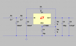
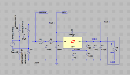
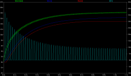
Since I did the schematic in LT Spice I went ahead and ran a simulation for fun.
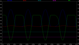
The node labels are at the top of the plot and the scale for the green current trace is at the right.
The blue is the capacitor charging voltage spike with the green showing a charging pulse of around 7 amps through the rectifiers. The rectifiers in the model are 25A units.
I picked an input VAC of 28V peak (I've added 0.5R series resistance to the voltage source, plus the two rectifier voltage drops give the 23.5V peak on the blue trace), which results in the output voltage of the second RC stage, presented to the LT1083, of about 16.5VDC. With the R3-R4 resistors setting the regulator at 15VDC out, that gives (16.5V - 15.0V) = 1.5V across the regulator here, near the 1.2V minimum the datasheet graphs show for 2.5A. The test load is 6R to draw the 2.5A.
You can see the ripple difference between the output of the first RC stage (red) at about 18.3VDC and the output of the second (auqa) at 16.5VDC. If I were to remove that second RC stage I would expect to see practically no difference in the regulated (magenta) output, with the regulator taking care of that slight amount of incoming ripple. By hey, this is diy audio and you already have the second capacitor, so might as well.
Messing around with the values a bit, the resultant 15V output still has some minor fluctuations in the sim if you zoom in a ways. Increasing the input voltage source slightly to 30V peak to allow more drop across the regulator fixes that, as I would expect, as does upping the output capacitor to 3300uF from 150uF. But this is just a sim of course - with the real part you might not even measure an output ripple difference at 1.5V across the part vs. the 3.5V.
Attachments
Last edited:
People tend to think adding more parts always sounds better, but if you want to know for sure get out the scope and read power line ripple at the base of the output transistors, that is the only place it matters. Let me take that back for a moment, other areas matter too, but you'd have those isolated from the large current swings on the rail to the output transistors (or integrated amp IC), not just a star ground since the +- rails are effected.
What you will find is that decoupling and filtering on the amp board itself swamps any other factor after the regulator subcircuit. There is a big difference between putting lots of capacitance on a regulated PSU versus an unregulated.
You most definitely do not need as many uF after a regulator as before it. Before it, you have a large time interval between each AC mains cycle, ie 50/60Hz bridge rectified to 100/120Hz. The capacitance needs be sufficient enough that the rail voltage stays above the minimum forward voltage drop across the regulator. The higher your input voltage is compared to the output voltage, the less capacitance you need to make that happen.
A regulator is far faster than 120Hz cycle time. For practical purposes, and especially considering trace and wire impedance from it to a large capacitor bank then on to the amp board, it is well documented and specified by the regulator manufacturers that you really don't need more than a very low impedance ~ 10-20uF capacitor after it. What then matters is impedance to the output transistor base, keeping your ESR between that regulator and the output transistor base as low as reasonably possible.
If by adding larger capacitors, you can get them closer to the output transistor base pin than the regulation circuit is, this is good, an improvement. If you still have an equivalent length/width/gauge trace or wire from the capacitor bank to the output transistor pin as you would if you left the capacitor bank out, it defeats the purpose.
What having a larger capacitance bank after a regulator can do, is spread out the duty cycle. Instead of dealing with shorter peak currents it deals with longer duration lower currents.
Now a word about what sounds better. I have been describing electrical function, not how something sounds. Maybe someone prefers less stable voltage, a slower more linear drop in voltage with momentary peaks... or maybe they don't. While people usually claim they *want* the opposite, I cannot argue with doing something and preferring the change in sound because that's what it is all about, the sound.
Last edited:
What having a larger capacitance bank after a regulator can do, is spread out the duty cycle. Instead of dealing with shorter peak currents it deals with longer duration lower currents.
I forgot to mention the larger inrush current upon turn on with the larger capacitance bank.
Have you also considered the AC line voltage and how much it changes over time? You need to make sure that the voltage headroom for the regulator is still there at low line and high load or you can loose regulation.
As for the difference in sound of reg v CRY I think that is mostly dodo with clipping onset and how the amp/ps deal with clipping,
As for the difference in sound of reg v CRY I think that is mostly dodo with clipping onset and how the amp/ps deal with clipping,
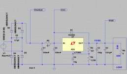
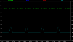
Here is the same thing with just a CRC filter. The lead resistor in that previous RCRC is really pretty useless other than reducing initial peak current through the rectifiers. Just results in a higher input voltage requirement with no real ripple improvement after the regulator. Here the voltage source peak is (just) 24VAC resulting in the same 16.5VDC going into the regulator. So there you go - you can use just the 2 big caps the the 0.7R you already have on hand.
The previous plot was steady state, of course. I've included the initial part of the plot here showing the 40A or so through the diodes while the (initially) uncharged capacitors charge up. In the previous RCRC circuit R1 reduces the initial current to about 20A.
Green is the output of the rectifiers going into the filter at about 18VDC. Blue is the output of the CRC filter going into the regulator. Red is the regulated output and aqua is the current through D3 - current scale is on the right side. The current plot in the previous post was through R1.
Attachments
Last edited:
BZed - I had thought about line voltage variation - I would not want to have an LDO regulator dropping only 1.5 volts if 1.2 is the minimum it can work with - I live in the countryside on a lightly loaded local transformer - the line voltage is generally high, but I can't count on it always being that way, especially if a local farmer plugs in something that pulls a lot of current and causes some violtage drop. I would prefer to see about 3 volts across the regulator (at 2.5 amps the regulator will only be disipating 7.5 watts, so no big deal on power losses especially bearing in mind it's a class A power amp anyhow).
! - Thanks for your interest in the thread - I concurr about getting some caps as close as possible to the output devices, but for me this isn't something I can easily do with the PCB layout i'm stuck with, though i'll see what i can do to upsize the 220uf's with something like 1000uf instead.
agdr - The rectifier diodes i'm using are rated 40 amps continuous when mounted on a suitable heatsink, mine are simply bolted to the chassis with some thermal grease, but given the low current draw i don't think the turnon current with only one resistor is going to hurt much, especially bearing in mind that there is a soft start on the primary sode fo the toroid. And thankyou very much for the sims - very informative!
Last edited:
- Status
- This old topic is closed. If you want to reopen this topic, contact a moderator using the "Report Post" button.
- Home
- Amplifiers
- Power Supplies
- Regulated supply for power amp