Is there any problem with using different sized capacitors in a power supply. For example if I wanted to build a CRC power supply could I use one large cap (a 100000uf) and a second smaller one (a 10000uf)? Would that cause any problems? Would it matter which cap is closest to the amp circuit and which one is farther?
Yes you can use different sizes and should, there is nothing but an arbitrary reason people use the same size caps except maybe that's what they have or they got a volume discount buying several of the same size... although I don't know what you mean by a CRC supply, that doesn't really tell us what it is besides having a resistor between two capacitors.
Is your design regulated or unregulated, what exactly is it? Generally the larger value capacitor would be farther from the amp circuit and the one closer would be either a boutique audio cap if you believe the hype that they sound different, OR one from a low ESR capacitor product group. Don't put a capacitor that is both small AND non-low ESR family group/type between the resistor and the amp, that would be the worst of all 3 choices, although I would not call 10,000uF small with a 100K uf before it unless your amp is exceeding a few hundred watts output.
Is your design regulated or unregulated, what exactly is it? Generally the larger value capacitor would be farther from the amp circuit and the one closer would be either a boutique audio cap if you believe the hype that they sound different, OR one from a low ESR capacitor product group. Don't put a capacitor that is both small AND non-low ESR family group/type between the resistor and the amp, that would be the worst of all 3 choices, although I would not call 10,000uF small with a 100K uf before it unless your amp is exceeding a few hundred watts output.
The type of power supply I would be trying this with would be an f5 power supply. I am going to be using a gigawork PS (blasphemy I know) and I thought I might replace or add extra caps right before the amp circuit. I was also looking at some large caps in the swap meet which I would use to build my own PS but I was curious if I could use them with other caps that were smaller so I could get everything to fit in my chassis.
I may be one of the few who never liked them small film caps
and I think it sounds perfect without, so why use them anyway
a super sized supply caps are not my favourites either
I tried real big ones once, and it was like they made the amp slow
but I know, it could have been other things doing it
and I think it sounds perfect without, so why use them anyway
a super sized supply caps are not my favourites either
I tried real big ones once, and it was like they made the amp slow
but I know, it could have been other things doing it
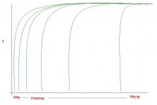
Why bypass?...On the attached graph, picture a lone electron at the far left of the curve..as it makes it journey away from the safety of its large capacitance it is venturing out onto the lone dangerous frontier of stray magnetic fields, & RF fields. The further it goes, it needs to be "reassured"......all the way to its final destination. The curves are wrong I'm sure......but the supply needs a low ESR out beyond 50K Htz.
_______________________________________________________Rick............
_______________________________________________________Rick............
Attachments
They do use higher ESR types out of cost considerations.....pile on the capacitance really high(With its own issues) to try to get the ESR down. Two high quality low ESR types will still get below multiples of the cheap ones. Bypassing just assures ESR stays down all along the line and at the higher frequencies
______________________________________________________Rick........
______________________________________________________Rick........
I have a theory but I am not sure if it is grounded.
My theory is this. You can build a PS with cheap caps but as long as you make the caps closest to the amp circuit high quality you will get 95% of the sound of a PS build with all high quality caps.
Has anyone ever tested this?
My theory is this. You can build a PS with cheap caps but as long as you make the caps closest to the amp circuit high quality you will get 95% of the sound of a PS build with all high quality caps.
Has anyone ever tested this?
^ People test that all the time when they receive some piece of consumer grade audio gear and upgrade the capacitors. A moment should be taken to talk about "quality" though, when you have a low frequency wave like right after the transformer and rectification, lowering capacitor bank ESR has diminishing returns, the difference in voltage rise/fall due to the capacitors is swamped by the input (doubled AC frequency, 50-60Hz -> 100-120Hz).
Your low ESR caps should be not just close to the amp circuit but as close as reasonably possible to the chip pins. Don't go rerouting audio signal traces and components to do it, keep them short as possible then power rail ESR as low as possible. The further away from your chip pins it is, especially with other capacitors closer, the more diminishing the return is from lowering ESR from capacitor choice - it becomes an ever smaller % of total ESR from the circuit traces and wires.
At the chip where it counts, most of the noise on the power rails is caused by the chip itself, high frequency noise so you want the low ESR @ KHz ranges and above. That's where the film or ceramic capacitors come in, you can get them really close to the chip pins. Next comes low ESR electrolytic just a little further away.
As for 95% of the sound, nobody can answer that because there are different views about what sounds best. If you could in theory design the absolute perfect PSU that resulted in rock steady power rails with no ripple whatsoever, some would still prefer the sound of something else with more power rail noise instead. Personally, I feel you'd get 95% of the sound quality using any (non-defective, average quality, not old dried out things) capacitors then putting a few 1uF or smaller film caps near the chip. 5% can be a lot though, consider one amp with 0.1% THD, and other with 5%... you can hear THAT 5% pretty easily. In the end all you can do is build, listen, swap parts and listen again. Different amps will have a different amount of change from such things.
Is there any problem with using different sized capacitors in a power supply. For example if I wanted to build a CRC power supply could I use one large cap (a 100000uf) and a second smaller one (a 10000uf)? Would that cause any problems? Would it matter which cap is closest to the amp circuit and which one is farther?
If your first cap is TOO awfully large, the initial inrush current might be too much. Check the current ratings on everything upstream, and the ripple-current rating of the cap itself. The inrush won't last long and many devices can exceed their max current ratings for a short time (but that should be verified in their datasheets). But also calculate or simulate the normal charging pulse currents, and make sure that the cap and everything upstream can handle them, since they will be happening all the time. Also, a higher ESR (equivalent series resistance) in the cap might make for more i-squared-r power dissipation, i.e. the cap might run too warm, possibly reducing its lifespan.
Caps are additive in parallel. The idea is to keep ESR down at all frequencies, and the environment is full of "pitfalls" the further away from the initial capacitance.
_____________________________________________________Rick........
I thought that a PS is DC so there are no frequencies that matter. Am i missing something here?
BTW thanks for all the help guys, I am slowly starting to understand some of the issues with power supplies that I didn't understand before.
^ Imagine a waveform like you have with AC, but that never dips below 0V so it's still DC. That's not what "all" the noise on the power rails is but any rise or fall above the nominal PSU voltage is occurring at some frequency, and frequency does matter to the extent of it being *dirty*(er) power which effects the amplification stage accuracy. Frequency doesn't have to mean rate at which voltage crosses a 0V threshold and goes negative.
In an amp you have noise from both ends. There is the AC power rectified which has a doubled noise frequency (100 v 120Hz depending on global location), then there is an irregular and constantly changing frequency caused by the impedance of the entire power supply chain versus the changing current flow through the output to the speakers.
In an amp you have noise from both ends. There is the AC power rectified which has a doubled noise frequency (100 v 120Hz depending on global location), then there is an irregular and constantly changing frequency caused by the impedance of the entire power supply chain versus the changing current flow through the output to the speakers.
Recommend you take a look at this, lots of good info.
Elliott Sound Products - Linear Power Supply Design
Mike
Elliott Sound Products - Linear Power Supply Design
Mike
This one has good basic information, too:
Unregulated Power Supply Design
If you add a regulator, just calculate the capacitance needed (per the link, based on your maximum load current) so that the voltage of the bottoms of the dips in the ripple voltage MINUS the regulator's output voltage never gets too close to the regulator's Dropout Voltage specification. Otherwise, the regulator's output gets very ugly when that happens.
I thought that a PS is DC so there are no frequencies that matter. Am i missing something here?
BTW thanks for all the help guys, I am slowly starting to understand some of the issues with power supplies that I didn't understand before.
You can get rid of most or almost all of the ripple from the AC-to-DC rectification process by using smoothing capacitors and optional voltage regulation. You can make the ripple amplitude as low as you want, literally.
But still, if your loads are not handling only unchanging DC, their current draws will not be constant. They would be time-varying.
In that case, either your power supply is big enough and has a low-enough output impedance to keep the supplied voltages perfectly constant, or, it can't. So that might be one reason that you could see something other than perfectly-constant DC on your power supply rails.
But besides that, there is parasitic inductance (just like the inductance that a coil has, but usually much smaller) literally everywhere that there's a conductive path, including the conductors between your power supply and your loads. And whenever a time-varying current flows through an inductance, a voltage is induced across the inductance that is equal to the time-rate-of-change of the current multiplied by the inductance. It's a physical law.
The induced voltages can have surprisingly-large magnitudes, even for small amounts of current and tiny inductances, because their magnitude is proportional to the RATE OF CHANGE of the current. So fast-edged pulses of current, even for very small amounts of current, can still induce relatively-large voltages. And there is also a portion of the voltage that's induced across the parasitic resistance of the conductors, according to Ohm's Law, i.e. V = I x R.
So, unless the loads are drawing unchanging DC currents, time-varying voltages will be induced across the distributed inductances (and resistances) of all of the conductors and other components, which will make each particular point on both the power rails and the ground return conductors appear to be "noisy", in terms of the voltage between any point and any other point in your circuit.
That's one very good reason to not let ground-return conductors share any length of conductor, and run them separately all the way back to the main smoothing capacitors. You wouldn't want the induced noisy voltages from high-current or fast-changing-current ground return conductors to appear as a noisy "ground" voltage back upstream at, for example, the ground reference pin for an amplifier's input. If it does, it will arithmetically sum with the input signal's voltage. That would be "a bad thing".
It's also probably the main reason to use BYPASS CAPACITORS on the power supply input pins for ICs and other current-consuming devices and circuits. The bypass caps act as small "point-of-load" power supplies.
When a device pin goes into a state where it suddenly wants to let current flow, an inductive power rail conductor would a) have a voltage induced across it by the changing current and b) might not allow the current to change as fast as it could. But with bypass caps within a millimeter or so of the pin, the sudden current demands can be supplied from the caps without the longer conductor's inductance effects.
So the bypass caps both prevent noise from forming on the power rails AND do a better job of letting things draw sudden changes in current. (Remember to connect the smallest bypass caps absolutely as close as possible to the pin being bypassed. A few millimeters is probably too far away.)
Choosing the sizes and types of bypass caps to use will matter, sometimes. But if you're not sure, for small-signal circuits just use a 10uF to 100uF electrolytic (not low ESR type) in parallel with a cheap 0.01uF to 0.1uF ceramic (not high quality types like NPO or C0G). The reason for not using higher-quality types is that they might cause resonances with the inductances of the power rail conductors and the higher ESR (equivalent series resistance) of the lower-quality caps will tend to damp those out so they don't "ring", or even oscillate.
If you feel that you need to use film-type or other very high quality bypass caps, but you don't know how to calculate or measure the parasitic inductances and the potential resonances and possibly design snubber circuits, then just insert a small-value resistor (say 3 to 100 Ohms, for small-signal circuits) in series with the power rail, just before the bypass caps (maybe try 10 Ohms, to start with). That could also have the advantage of forming an RC low-pass RF filter. For high-power circuits, you probably can't insert a resistor, there. So you have to be very careful or lucky.
Regarding the ESR of electrolytic capacitors, remember that it changes, a lot, when the signal frequency changes. So you might only need special "low ESR" electrolytics if you are worried about the ESR at low frequencies, such as the 120 Hz ripple from a rectifier in a power supply. For example, a 33 uF electrolytic cap might have an ESR of 3.3 Ohms at 120 Hz. But at 1800 Hz its ESR would be around 0.2 Ohms. Elecrolytics' ESRs also change a lot with temperature. (If you have a cap's ESR spec at one frequency, you can calculate its DF (dissipation factor) with DF = 2 Pi f C ESR. The DF usually only changes by about 2-to-1 overall, so you can then use the DF to roughly calculate the ESR at any other frequency, with ESR = DF / 2 Pi f C .)
Other stuff can get into your circuit, too. And it WILL. There will be both conducted and radiated time-varying "junk" that will get in, which will usually be of two types: power-line AC and RF (radio frequency).
For radiated electromagnetic waves, of both RF and power-line (and all other) types, "everything is an input", including outputs, inputs, power connections, and ground connections, as well as every bit of wire and PCB trace and even the components in your circuit.
If you realize that a LOOP made of any conductor will have a time-varying current induced in it whenever the loop is in a time-varying electromagnetic field, and that the reverse is also true, such that any loop with a time-varying current in it will RADIATE a time-varying electromagnetic field, then you will start to see ways to make your circuits MUCH quieter.
How bad it gets depends on the geometric AREA that the loop encompasses. You want any loops to encompass as little area as possible. So the way to do that, in our circuits, is to keep ALL "pairs" of conductors as close together as possible, all the time. For example, if you have a diy power amplifier and it has signal input and signal input ground conductors, those will need to stay absolutely as close together as possible, everywhere. If they are wires, twist the two wires together, tightly, all the way to each end. Better yet, use twisted pair cables that also have a shield around them and connect the shield to the chassis only on the input end. Also twist your AC power input pair, to the transformer, and the transformer output pairs, and DC power/ground pairs, and every other pair. On PC boards, either keep the traces right next to each other or put them on more than one layer and run them right above and below each other (or, usually better yet, use entire layers as power and ground planes).
Your grounding scheme will also have to be right, to not make loops. If every signal or power conductor has it own separate ground-return conductor, it's much easier to always keep them close together. Do searches for "star grounding" but realize that most people don't remember that the other conductor of the pair should be paired with each ground return and kept as close as possible to it, everywhere.
At the same time, also do the obvious stuff like keeping the small-signal and DC power conductors as far away as possible from AC and other fast-changing or high-current conductors and devices.
For mitigating RF, the most-obvious thing to do is to always put a low-pass filter just upstream from every IC input (which also includes outputs and power pins). A small resistance and a capacitor to ground is one way. But there are nuances that are beyond the scope of this post. See ADI - Analog Dialogue | Op Amp Applications Handbook, especially section 7.
Also, keep conductors as short as possible, and keep loop areas as small as possible, so your circuit doesn't look like good RF antennas, to the RF.
RF (which can also be produced by things like a light switch being flipped) can do seemingly-unpredictable things, when semiconductors are in a circuit. The RF gets rectified by every semiconductor junction it encounters. That can cause a myriad of problems, some obvious and some not. It might simply cause a slight (or not) change in the DC operating points in the circuitry inside of an IC. Or it might cause large spurious voltages at an amplifier IC's output. It can alter the performance of ICs and other semiconductor circuits in subtle ways that you might never realize are occurring, or that only occur at certain times with no obvious cause, but that are still degrading your circuit's performance. A good audio circuit design always includes low-pass RF filters on basically every opamp's inputs, for example, and on all ICs' DC power inputs, and on all amplifier outputs.
Sorry to have blathered-on about all of that, for so long. I realize that you won't be able to digest it all, right now, and might not need a lot of it until some point in the future. But at least now it's here, so you can reference it if you ever do need it.
Cheers,
Tom
Last edited:
- Status
- This old topic is closed. If you want to reopen this topic, contact a moderator using the "Report Post" button.
- Home
- Amplifiers
- Power Supplies
- Are different sized power supply caps ok?