Does it make sense to use a secondary winding from an SMPS to control the bypass device of the inrush circuitry? For example, if the design has a bias winding to supply the PWM chip, why not use it to also drive a bypass relay or triac?
I've been looking through a lot of the inrush posts but have not seen this method (maybe I missed it).
gene
I've been looking through a lot of the inrush posts but have not seen this method (maybe I missed it).
gene
Now examine what will happen if the output is short.
OKay - I see what you are getting at, but . . .
Output is short, PWM goes into cycle-by-cycle limiting, bias-winding never reaches designed level, so inrush circuit stays active. Depending on PWM design, the system will be calling for maximum current, and will stay that way - so the inrush limter takes a beating. But what if the PWM goes into hiccup mode - maybe the power consumed by the inrush limiter is ok.
On the other hand - maybe it's better to keep the inrush limiter active just long enough to fully charge the input capacitors - keeping the PWM inactive until that is done
Inrush limiting resistors are never rated for any steady state. There may be several times more power dissipated in them for a short time, so for me it is vital to ensure they are bypassed after calculted time. Bypassing them too early risks some inrush, which may or may not be a problem, keeping the bypass open for too long, while the load wants to consume the power is a direct fire risk.
That's why I think your proposed solution won't get my favourite.
That's why I think your proposed solution won't get my favourite.
Inrush limiting resistors are never rated for any steady state. There may be several times more power dissipated in them for a short time, so for me it is vital to ensure they are bypassed after calculted time. Bypassing them too early risks some inrush, which may or may not be a problem, keeping the bypass open for too long, while the load wants to consume the power is a direct fire risk.
That's why I think your proposed solution won't get my favourite.
So what about NTC, with relay bypass activated after SMPS comes alive? NTC do not have the fire hazard problem. Seems pretty like a simple solution.
there is no reason at all that you cannot do as you said in your first post.
..i.e. using a turn on the trafo to give you power to switch your bypass FET.
You are right.......short circuti on output will take the pwm controller into hiccup mode, so no worries for your inrush resistor overheating.
..i.e. using a turn on the trafo to give you power to switch your bypass FET.
You are right.......short circuti on output will take the pwm controller into hiccup mode, so no worries for your inrush resistor overheating.
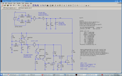
Here's something I've worked on - what do you all think? The circuit has 3 section:
1) top portion is the AC to DC section
2) middle left is a 10 Volt regulator
3) center bottom is a timer
4) bottom right UVLO
R1 is either NTC or power resistor to control inrush. Not shown yet is a bypass arrangement - either relay or triac, for example.
Okay - operation goes something like this:
AC power is applied. At t=0, J1 is conducting, which holds UVLO low.
That keeps my PWM in reset. As the DC rises (Vout), the 10 volt regulator
fires. That starts up the timer circuit. R7 and C4 set the ramp rate. This thing
is very low current operation. When Vtest reaches 2.5Vdc, the TL431 conducts.
This brings the gate of M2 low enough to turn it on, and now the gate of J1 goes
high, turning J1 off. Now the UVLO circuit works normally, and the PWM is out
of reset.
I've got the time constant set to around 1.5 seconds. It can be any time - very easy to adjust.
Stuff not shown:
1) PWM bias supply. It has to be greater than 10V, and connects to V10 through a diode. So when it becomes active, it turns off Q1 and Q2, and now supplies the timer circuit and keeps things status-quo.
2) Bypass for NTC. I think it would run from the V10 supply, use a transistor to turn it on, and use the signal at gate of J1 to control it.
Stuff that I don't like:
1) Q2 consumes a lot of power when it's on - like 40W in this example. That assumes a load of 100 mA. That's probably way overkill - also the time it is active is only 1.5 seconds. Once the PWM is running, there is no power consumption. In any case, I plan to use a package that can handle this.
2) R4 also is a power hog - just not quite so bad. Maybe .75 Watts. In this diagram, it will always be active even after PWM is running. Maybe should add something to turn it off.
Attachments
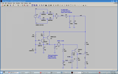
Some changes to the prior circuit. The JFET did not turn all the way off, so the UVLO feature wasn't correct. Also, I removed the current source timer in favor of simple R-C timer.
R1 is either NTC or power resistor to control inrush. Not shown is a relay across it.
Q1, Q2, R4, R5, C3, D5 are a 10 Volt startup supply. It is capable of 100 mA, maybe more.
I2 is an arbitrary load on the startup power supply.
R7, C4 are the timer.
U1 (TL431) used as comparator, has snap-action turn-on when the gate is > 2.5Volts. R7-C4 timer sets the delay before U1 fires.
Q4 acts as a switch. Off when U1 hasn't fired, on when U1 is on.
R6 is equivalent coil resistance of a relay. It's off when Q4 is off.
R3, R2, U2 are used for UVLO. When Q4 is off, gate voltage is ground, so the SCR is off, and UVLO is ground. That keeps my PWM in reset. When Q4 is on, the SCR switches on and UVLO follows the main voltage and UVLO works as expected.
The whole thing snaps on and off, instead of gradual turn-on/off.
This is close to what I was looking for.
Attachments
- Status
- This old topic is closed. If you want to reopen this topic, contact a moderator using the "Report Post" button.
- Home
- Amplifiers
- Power Supplies
- inrush bypass using smps output