Hi there,
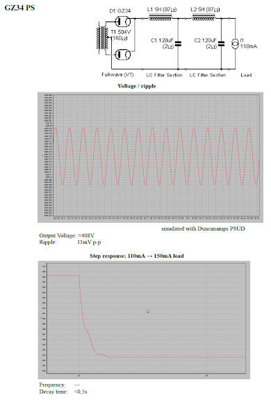
just finished a test setup for a power supply, schematic as follows:

In PSUD2 the circuit simulates quite well, about 11mV ripple at "A" and an acceptable step response:
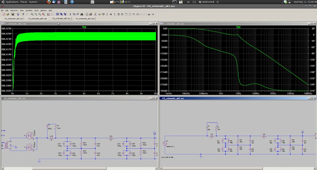
A simulation in LTSpice went quite weird - the ripple is still the same, but the output oscillates wildly at low frequencies about 1-5Hz:

Guess which one Mr. Murphy has chosen to be closest to reality?
Ideas anyone?
Greetings,
Andreas
just finished a test setup for a power supply, schematic as follows:
In PSUD2 the circuit simulates quite well, about 11mV ripple at "A" and an acceptable step response:
A simulation in LTSpice went quite weird - the ripple is still the same, but the output oscillates wildly at low frequencies about 1-5Hz:
Guess which one Mr. Murphy has chosen to be closest to reality?
Ideas anyone?
Greetings,
Andreas
I guess you need to tame the LC resonances. In your first schematic I would try adding 200 ohms resistance in series with L22. Or maybe some resistance in series with both coils. Your second circuit shows 87 ohms with each coil. Maybe that's why it behaves better.
The other damping option is to put resistors (maybe 100 ohms?) in series with each of C21, C23, C27 and C29. That will give more ripple but less voltage drop.
The other damping option is to put resistors (maybe 100 ohms?) in series with each of C21, C23, C27 and C29. That will give more ripple but less voltage drop.
Hi there,
yes, trying to damp the resonances will probably be the next step.
Still I wonder about the strange irregular shape of the oscillation. I ran a FFT on the simulated data and it shows no predominant frequency apart from the 100Hz + harmonics. The large oscillation "above" the ripple seems to be completely random.
Would one expect that?
The difference between the two simulations seems to be the ESR of the caps - PSUD2 regards them to be 2 ohms per default. Current production electrolytics probably have milliohms. I will try adding series resistances and see what happens.
Other ideas?
Greetings from Germany,
Andreas
@godfrey: The chokes have 87Ohm DC resistance in both cases, although not stated explicitly...
You have a 2-cell lumped approximation to an unterminated transmission line, with a characteristic impedance of 204 ohms and cutoff around 6.5Hz. It is shorted at one end by the rectifiers and open-circuit at the other end, so will ring like a bell. Two things to try: change one of the L's or C's so they are not matched, or add a snubber across one of the caps (say, 100 ohms in series with 50-100uF?).
You have a 2-cell lumped approximation to an unterminated transmission line, with a characteristic impedance of 204 ohms and cutoff around 6.5Hz. It is shorted at one end by the rectifiers and open-circuit at the other end, so will ring like a bell.
Hi DF96,
I am not sure I fully understand your point. The other end of the filter chain was terminated by the load resistance (ca. 4,5kOhm). This is not well-matched, but should not act as an open end either.
What do you think?
Greetings,
Andreas
Your PSUD2 simulation shows a fixed current load, not a resistance. A fixed current load has infinite resistance, so to AC looks like an open circuit. In any case, 4.5k is almost open circuit when compared with 204ohms.
You will be getting some damping from the choke resistance and the rectifiers. I think the basic problem is that by 'traditional' valve standards the PSU has too low impedance for the applied load. This seems to be a common problem nowadays, as big caps are available. In the olden days you might have had 16uF or 32uF caps with a 10-15H choke. This would have a higher resonance frequency, but would be higher impedance so better damped by the load.
You will be getting some damping from the choke resistance and the rectifiers. I think the basic problem is that by 'traditional' valve standards the PSU has too low impedance for the applied load. This seems to be a common problem nowadays, as big caps are available. In the olden days you might have had 16uF or 32uF caps with a 10-15H choke. This would have a higher resonance frequency, but would be higher impedance so better damped by the load.
Your PSUD2 simulation shows a fixed current load, not a resistance. A fixed current load has infinite resistance, so to AC looks like an open circuit. In any case, 4.5k is almost open circuit when compared with 204ohms.
Hi DF,
the problem is, the PSUD2 simulation with the o.c. condition does *not* show the strange behaviour... Even the step response shows much less ringing than the original "commercial" supply. Still thinking about the 2ohms ESR PSUD2 uses..?
I would like to find out why PSUD2 and LTSpice give different results, and what is needed to give the real-world response PSUD2 predicted....
Greetings,
Andreas
There doesn't seem to be enough non-linearity in the circuit to provoke a chaotic response, even though that is what LTspice seems to be doing.
The crazy thing is, not only LTSpice is doing this, reality has chosen to do the same...
Andreas
PS. Changing the ESR does not lead to any significant change in the results, tested it.
It's not clear which ESR you're talking about. The one on the caps or the one on the inductors?
I suggest that you dampen the Q of your resonant circuit to somewhere around 0.5.
QL = XL/ESR; XL = 2*pi*f*L
I take you're running 50 Hz mains, so f would be 100 Hz (full-wave rectifier). So, let's make QL = 0.5 -->
XL/ESR = 0.5 --> (2*pi*f*L)/ESR = 0.5 --> ESR = (2*pi*100*5)/0.5 = 6.3 kOhm. Subtract the DC resistance of your choke and insert the resulting resistance in series with the inductor.
Try it in SPICE first...
~Tom
Still thinking about the 2ohms ESR PSUD2 uses..?
PSUD doesn't "use" any value for ESR. That's just the initial, or sample value for the most basic model - some value has to be there. You don't use the initial values for any other specification, why would you use the sample value for ESR? Enter your actual values. Some manufacturers list the values on their spec sheets.
Sheldon
Solution?
Hi there,
at least in the simulation, bypassing the first choke with [500nF + 1.8kohms in series] tamed the random oscillation, see below:
HF response is slightly worse, but should still be ok. I'll get to my scrapbox full of small caps and find me a nice one to test if simulation passes the test against reality^^
Greetings,
Andreas
- Status
- This old topic is closed. If you want to reopen this topic, contact a moderator using the "Report Post" button.
- Home
- Amplifiers
- Power Supplies
- PSU problem - Murphy is an ***hole!