Second, I do not have any schematics whatsoever for my amp (Alamo 2525), and after many fruitless hours of web surfing, I don't think any exist.
The amp uses an old radio amp setup with a 35w4 diode rectifier, a 50c5 pentode output, and a 12au6 pentode preamp. I am attempting to install an isolation transformer to fix the grounding issue (the current was essentially being grounded into the chassis), and I have run into a problem with trying to counteract the half-wave rectification of the 35w4. The plan is to run the wall plug into the primary leads of the isolation transformer, and then run the secondary leads into a bridge rectifier before continuing into the tube rectifier. The bridge rectifier only gives us one lead which, currently, is intended to run directly into the tube rectifier. The problem is that I'm not sure where the lead to the power switch is supposed to come from. I don't know how to wire the on/off leads with all the leads from the transformer currently accounted for. I am using a Triad N68X isolation transformer, and here is the link to the article / schematic I have been using:
Fixing the half-wave rectifier problem
DF96: The isolation transformer wouldn't be able to handle the half-wave rectification because the 35w4 sends back the negative current to the transformer, which causes it the transformer to have a standing DC voltage and become saturated much quicker. By creating a full wave rectification, it takes out the negative current that is being sent back to the transformer.
Leadbelly: the problem with the on/off switch is that it is one of those volume/switch combo pots that you see on some older amps where all you do to turn on the amp is turn the volume knob. I can't include the pot before the transformer like the diagram says because the pot is connected to the rest of the amp circuit, leaving no output lead available to connect to the transformer. If I had a schematic, I could probably figure out some way to rewire the chassis, or see if there was another available solution, but I can't find one and the physical wiring of the chassis itself is very confusing and many of the components are old, faded, and unreadable (although still in working condition). If I used one secondary lead from the transformer to connect to the pot, and then one lead connect to both sides of the bridge, would that possibly work?
Also, I've looked a thousand times at the wiring and I'm slowly in the process of creating my own hand-drawn schematic, but I've never be able to find the source of the current that is somehow entering the chassis and causing 100+ volts to run through the chassis whenever the amp is on. Any suggestions on what/where I should look at, or another explanation as to why this is happening?
Leadbelly: the problem with the on/off switch is that it is one of those volume/switch combo pots that you see on some older amps where all you do to turn on the amp is turn the volume knob. I can't include the pot before the transformer like the diagram says because the pot is connected to the rest of the amp circuit, leaving no output lead available to connect to the transformer. If I had a schematic, I could probably figure out some way to rewire the chassis, or see if there was another available solution, but I can't find one and the physical wiring of the chassis itself is very confusing and many of the components are old, faded, and unreadable (although still in working condition). If I used one secondary lead from the transformer to connect to the pot, and then one lead connect to both sides of the bridge, would that possibly work?
No, I still think you're misdiagnosing. That pot should have 3 lugs for the variable resistance function and a separate set of lugs to do the on/off switching. All you need to do is figure out which leads are for the switch and which leads are for the variable resistance. All you need is 2 minutes with a multimeter.
The DC in the secondary will be balanced by DC in the primary. This is quite a different situation from applying a standing DC voltage to a transformer - in that case there is no balancing current in the other winding. Using an isolation transformer to power an AC/DC circuit is a standard servicing procedure, used for years. It provides both safety and the ability to connect test equipment.
Also, I've looked a thousand times at the wiring and I'm slowly in the process of creating my own hand-drawn schematic, but I've never be able to find the source of the current that is somehow entering the chassis and causing 100+ volts to run through the chassis whenever the amp is on. Any suggestions on what/where I should look at, or another explanation as to why this is happening?
I assume you are measuring that 100+ V with a multimeter? It's just the charge on the chassis through a small cap from the line connections. Standard in the old days. It's high impedance, not the dead short you are probably worried about. Still, don't use it until you get your mod sorted out to a proper, modern grounding system.
No, I still think you're misdiagnosing. That pot should have 3 lugs for the variable resistance function and a separate set of lugs to do the on/off switching. All you need to do is figure out which leads are for the switch and which leads are for the variable resistance. All you need is 2 minutes with a multimeter.
I've already located the two lugs for the on/off switch. They are situated on the circular back of the pot, where as the the variable resistance lugs are the three on the side of the pot. One of the on/off lugs was connected to the black (hot) wire from the wall, and the other has a wire leading to a small perf board with a capacitor and resistor, which then connects to two additional wires which lead to the filter cap and power tube separately. The variable lugs are also incorporated into the wiring, with one of them wired to the preamp tube, one wired to the power tube, and the other wired to the afore-mentioned perf board. I don't know how I would go about rewiring the power to allow for the circuit shown in the diagram.
The DC in the secondary will be balanced by DC in the primary. This is quite a different situation from applying a standing DC voltage to a transformer - in that case there is no balancing current in the other winding. Using an isolation transformer to power an AC/DC circuit is a standard servicing procedure, used for years. It provides both safety and the ability to connect test equipment.
So, if I didn't need to worry about creating a full wave rectification, would I be able to attach one of the secondary leads from the transformer to the on/off lug on the pot and the other to the rectifier tube? I know that will cause the transformer to receive power as long as the amp is plugged in, but the main issues I'm trying to fix with the isolation transformer is the grounding problem and noise when the amp is turned on.
I've already located the two lugs for the on/off switch. They are situated on the circular back of the pot, where as the the variable resistance lugs are the three on the side of the pot. One of the on/off lugs was connected to the black (hot) wire from the wall, and the other has a wire leading to a small perf board with a capacitor and resistor, which then connects to two additional wires which lead to the filter cap and power tube separately. The variable lugs are also incorporated into the wiring, with one of them wired to the preamp tube, one wired to the power tube, and the other wired to the afore-mentioned perf board. I don't know how I would go about rewiring the power to allow for the circuit shown in the diagram.
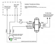
Think of all the lines as wires. Think of everything coming before the tube rectifier as new wires. If you look at the at th symbol for the "on/off switch" on the drawing I attached, you will see that it has 2 black dots. Think of those 2 black dots as the 2 physical on/off lugs on the switch. Direction doesn't matter. You would connect one lug to the hot wire of your new 3 prong power cord. You would connect the other lug to the fuse with a wire as shown in the drawing.
Okay. I understand everything that you've said so far, but I'm still confused about the current wires/connections attached to the 2nd on/off lug on the pot. Where does the wire that is currently attached to the 2nd lug need to be reattached within the amp? Or can that wire be removed completely without effecting the performance of the amp? I'll try and finish up my hand drawn schematic so I can show you exactly what I mean.
Speedy,
As I stated in this thread, replace the OEM series heater string dropping resistor with a 10 W./150 Ω and 1/2 W./3.3 Ω combination and be certain you are safe with today's higher average mains voltage.
DON'T connect the heater setup to anything associated with DC. Connect it directly to the secondary of the N-68X. Doing so avoids any possibility of over voltage on the heaters. Perhaps the heating effect of the rectified waveform is the same as a sine wave, but why take a needless risk?
The on/off switch should be on the primary side of the isolation trafo. Incorporate a 1/2 A. slow blow fuse in the primary side circuitry too. That's what LB correctly points out.
BTW, without a SS bridge, how hot does the N-68X get? Is it so hot that you can't touch it at all or is it hot to the touch and you need to take your hand away after a short interval? If it's the later, the SS bridge is not really necessary, as the trafo is built to take a fair amount of heat.
Last edited:
Where does the wire that is currently attached to the 2nd lug need to be reattached within the amp? Or can that wire be removed completely without effecting the performance of the amp? I'll try and finish up my hand drawn schematic so I can show you exactly what I mean.
Well, where is the other end of that wire connect to now? It must either be going to the tube rectifier, the fuse holder, or the power cord. That tells you where to rewire it to. I don't know how I can spell it out any more. Imagine the lines on the schematic are wires , either remove them all and rewire from scratch, or only undo one end each and rewire to match the schematic, and only add new wires where you have to.
ToddFun.com Blog Archive Isolation Transformers
If you want to know how to safely use an isolation transformer, watch this clip. It is very good.
ToddFun.com Blog Archive Isolation Transformers
If you want to know how to safely use an isolation transformer, watch this clip. It is very good.
ToddFun.com Blog Archive Isolation Transformers
I apologize for not responding sooner. With mother's day weekend and finals week, I'm pretty swamped. Anyway...
I took a picture of the wiring in the chassis with my laptop camera, so the quality isn't great, but it is enough to give a rough idea of the layout. I am also finishing the schematic, so I will post that up soon. I am going to try and wire the amp without the SS bridge first, using one of the secondary leads to go to the on/off lug and the other to the rectifier and see how that works. If the iso tranny gets too hot, then I'll see about rewiring the amp to allow the on/off switch to be wired before the tranny and then wire the secondary leads to the SS bridge, then the SS bridge to the rectifier, etc.
 [/URL][/IMG]
I took a picture of the wiring in the chassis with my laptop camera, so the quality isn't great, but it is enough to give a rough idea of the layout. I am also finishing the schematic, so I will post that up soon. I am going to try and wire the amp without the SS bridge first, using one of the secondary leads to go to the on/off lug and the other to the rectifier and see how that works. If the iso tranny gets too hot, then I'll see about rewiring the amp to allow the on/off switch to be wired before the tranny and then wire the secondary leads to the SS bridge, then the SS bridge to the rectifier, etc.
- Status
- This old topic is closed. If you want to reopen this topic, contact a moderator using the "Report Post" button.
- Home
- Amplifiers
- Power Supplies
- Isolation transformation wiring project help