sorry wintermute for repeating this, I really should have read the thread to the end....
No Problem at all hesener!! I'd much rather someone repeat something when I've made a mistake than not say something
") I'm a big boy and can handle the truth
I'm a big boy and can handle the truth I always feel bad if I post something technically incorrect and am happy for people to point it out.
Tony.
I understood the idea was omitting any regulator to improve sound quality....
Sorry, but I thought the whole idea behind a regulator was to improve sound quality. You disagree with that?
The problem with regulators can be poor design, mostly for not taking care of dynamics. Even if that limitation sometimes is on the cicuit the regulator is feeding.
Hi! All,
I just build a proto of the P3A amp, it sounds fantastic but my problem was the PSU. I have a dual supply 36vac toroid rated at 500w and I have read (Elliotts site) that the maximum rail voltage for the P3A was -/+42vdc. 36vac converted to dc becomes 50vdc, it looks too much for the amp to handle. Adding outputs in parallel my do the job but I only wanted an output power of about 80-100w at 8ohms load. (sufficient enough for home use)
Anyway...anyone can suggest me a simple (no IC regulators) RCRC filter circuit for my toroid in hand? I guess it just need to drop some voltage and come up to -/+42vdc. Sorry I can't do simulations.
Thanks!


I just build a proto of the P3A amp, it sounds fantastic but my problem was the PSU. I have a dual supply 36vac toroid rated at 500w and I have read (Elliotts site) that the maximum rail voltage for the P3A was -/+42vdc. 36vac converted to dc becomes 50vdc, it looks too much for the amp to handle. Adding outputs in parallel my do the job but I only wanted an output power of about 80-100w at 8ohms load. (sufficient enough for home use
)Anyway...anyone can suggest me a simple (no IC regulators) RCRC filter circuit for my toroid in hand? I guess it just need to drop some voltage and come up to -/+42vdc. Sorry I can't do simulations.
Thanks!
Last edited:
I think that the problem you will run into is that the voltage drop is dependent on current draw. As the P3A is a class AB amp it doesn't have a constant current draw.
with a regulated supply it is less of an issue provided that the maximum current possible is used to calculate the voltage drop (and that remains higher than the dropout voltage of the regulator).
With an unregulated supply you would need to go with the lowest current draw (to get the voltage down to your required 42V but then when current demands increase your voltage will sag a lot more.
Generally with Class AB amps CRC is done with very low value resistors (less than 1/2 ohm) to ensure that voltage drop is minimal, and heat dissipation is also minimal.
Someone else more experienced than I may have another suggestion, but I think your best bet is a new transformer
Tony.
BEST RC FILTER FOR AMP PS
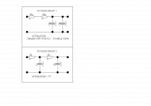
Can anyone tell me which of the two attached power supply filters has the greatest attenuation at 100Hz?
I know ( I hope! ) how to calculate the first circuit but not the second, can someone please take the time to explain the calculation to me.
Thanking you in advance.
Gordon.
Edit: All the resistors are 1 ohm, its not very clear in the diagram.
Edit 2: The capacitors are low ESR so Zc = Xc, more or less. Where Xc = 1/(2*pi*f*c).
Attachments
Last edited:
If the reactance of the capacitor is significantly lower than the resistance of the resistor then you can calculate the second circuit as just two separate circuits connected together. The net reduction in ripple is the product of the reduction from each sub-circuit. So you get
20 log (Xc^2/(R^2+Xc^2))
If the condition in my first sentence is not satisfied then you just have to slog out a full network calculation or simulate it.
20 log (Xc^2/(R^2+Xc^2))
If the condition in my first sentence is not satisfied then you just have to slog out a full network calculation or simulate it.
Thanks, DF96. By the approximation, the second circuit only has 14.5 dB of attenuation, however the value of Xc is only about 1/2 the resistor value so the result will be innacurate, presumably the real circuit would have more attenuation due to the second stage loading the first.
I can't simulate as I'm on an android tablet ( unless anyone knows of an android OS circuit simulator! I really need to try and fix one of my broken laptops, so that I can get back on tinycad and ltspice. )
To be honest I think I'll just build it and take measurements!
I can't simulate as I'm on an android tablet ( unless anyone knows of an android OS circuit simulator! I really need to try and fix one of my broken laptops, so that I can get back on tinycad and ltspice. )
To be honest I think I'll just build it and take measurements!
Last edited:
2 Stage RC power supply filter
See attached, Courtesy of :
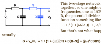
Second-order RC networks
I've forgotten how to manipulate complex numbers Can anyone explain how to use that equation,
Regards,
Gordon.
See attached, Courtesy of :
Second-order RC networks
I've forgotten how to manipulate complex numbers
Can anyone explain how to use that equation,Regards,
Gordon.
Attachments
If an RC circuit provides a significant amount of attenuation then cascading two of them will give you much more attenuation - the product (or double the dB). If it doesn't, then simply doubling up the components (as in your first circuit) is better, as this will give approximately four times the attenuation (or 12dB better) of a single RC.
To use complex numbers just treat j as if it was algebra. If the final result has j in the denominator (plus a real part) then you need to get rid of it by multiplying the top and bottom by the complex conjugate. So
1/(p+jq) = (p-jq)/[(p+jq)(p-jq)] = (p-jq)/[p^2+j^2]
Then wherever you see j^2 in the result replace it by -1.
If an RC circuit provides a significant amount of attenuation then cascading two of them will give you much more attenuation - the product (or double the dB). If it doesn't, then simply doubling up the components (as in your first circuit) is better, as this will give approximately four times the attenuation (or 12dB better) of a single RC.
To use complex numbers just treat j as if it was algebra. If the final result has j in the denominator (plus a real part) then you need to get rid of it by multiplying the top and bottom by the complex conjugate. So
1/(p+jq) = (p-jq)/[(p+jq)(p-jq)] = (p-jq)/[p^2+j^2]
Then wherever you see j^2 in the result replace it by -1.
Thanks DF96, another member kindly supplied the solution, I could probably have slogged through the Maths, but it would've been painfully slow!
Gordon.
- Status
- This old topic is closed. If you want to reopen this topic, contact a moderator using the "Report Post" button.
- Home
- Amplifiers
- Power Supplies
- Need help on RC filter for power supply